


5-15
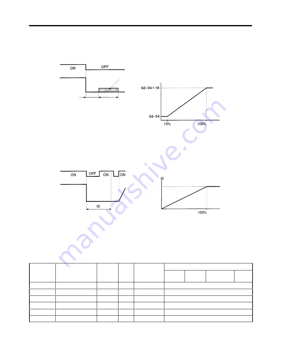
DC Braking Stop (b1-03 = 2)
(DC Injection)
Note: Lengthen the min. baseblock time (L2-03) when an over-
current (OC) occurs during stopping. When the power to
an induction motor is turned off, the counter-electromotive
force generated by the residual magnetic field in the mo-
tor can cause an overcurrent to be detected when DC
braking is applied.
Note: After the stop command is input and the minimum baseblock
time (L2-03) has elapsed, DC braking is applied and the motor
stopped. The DC braking time depends upon the output fre-
quency when the stop command is input and the “DC braking
time at stop” setting in b2-04, as shown in the graph below.
DC braking
Output frequency
Run command
Min. baseblock time (L2-03)
DC braking time
DC braking time
(Max. frequency)
Output frequency
when the stop
command is input
Free-run Stop with Timer (b1-03 = 3)
Note: After the stop command is input, run commands
are ignored until the time t
0
has elapsed. The time
t
0
depends upon the output frequency when the
stop command is input and the deceleration time.
Output frequency
Run command
(Max. frequency)
Output frequency
when the stop
command is input
Time
Deceleration
time
5-1-8 Multi-function Input Settings (H1-01 through H1-06)
Parameters H1-01 through H1-06 set the multi-function inputs in accordance with the application. Thes-
e 6 parameters cannot be changed during operation.
Parameter
Display name
Setting
Units
Default
S
Valid access levels
number
p y
g
range
setting (See
note.)
V/f
Control
V/f with
PG
Open Loop
Vector
Flux
Vector
H1-01
Terminal 3 Sel
0 to 77
---
24
Basic or Advanced
H1-02
Terminal 4 Sel
0 to 77
---
14
Basic or Advanced
H1-03
Terminal 5 Sel
0 to 77
---
3 (0)
Basic or Advanced
H1-04
Terminal 6 Sel
0 to 77
---
4 (3)
Basic or Advanced
H1-05
Terminal 7 Sel
0 to 77
---
6 (4)
Basic or Advanced
H1-06
Terminal 8 Sel
0 to 77
---
8 (6)
Basic or Advanced
Note The default settings in parentheses are the default values when the Unit is initialized for 3-wire
sequence control with A1-03.
Basic Operation
Chapter 5
Summary of Contents for SYSDRIVE 3G3FV
Page 1: ...USER S MANUAL High function General purpose Inverter SYSDRIVE 3G3FV Cat No I516 E1 4 ...
Page 16: ...Chapter 1 Introduction 1 1 Function 1 2 Nomenclature 1 3 New Functions 1 ...
Page 33: ...Chapter 2 Installation 2 1 Mounting 2 2 Wiring 2 ...
Page 112: ...Chapter 4 Trial Operation 4 1 Procedure 4 2 Operation Example 4 ...
Page 289: ...Chapter 7 Parameter Lists 7 1 Initialize Mode Parameters 7 2 Program Mode Parameter List 7 ...
Page 366: ...Chapter 9 Specifications 9 1 Inverter Specifications 9 2 Option Specifications 9 ...
Page 395: ...Chapter 10 Appendix 10 1 Notes on Using the Inverter for a Motor 10 ...