5-52
The multi-function analog outputs have the following functions with these parameter settings. Ter-
minal 22 is the multi-function analog output common. (There are separate commons, terminals 27
and 37, for the 3G3FV-
-CUE/CE.)
Multi-function analog output 1 (terminal 21): Outputs the Inverter’s ASR input (0 to
±
10 V).
Multi-function analog output 2 (terminal 23): Outputs the actual motor speed (0 to
±
10 V).
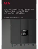
We recommend monitoring both the ASR input and the motor speed in order to observe a response
delay or deviation from the reference value, as shown in the following diagram.
Motor speed
ASR input command
Motor speed (response)
Time
3. Give acceleration/deceleration commands and adjust the gain while observing the waveform.
Motor
speed
If overshooting occurs:
Decrease C5-01 and increase C5-02.
If undershooting occurs:
Decrease C5-03 and increase C5-04.
4. If the overshooting or undershooting can’t be eliminated by adjusting the gain, decrease the ASR
limit (C5-05) to lower the frequency reference compensation limit. Since C5-05 can’t be changed
during operation, stop the Inverter’s operation and then decrease the ASR limit by 0.5 (%). Perform
step 3 again after the setting has been changed.
The ASR limit is the frequency limit for compensation by speed control loop. Set this frequency limit
as a percentage of the maximum output frequency. If the frequency limit is lowered too much, the
motor speed might not reach the target speed. Verify that the target speed is reached during normal
operation.
Parameter
Display
Setting
Units
Default
Valid access levels*
number
p y
name
g
range
setting
V/f
Control
V/f with
PG
Open Loop
Vector
Flux
Vector
C5-05
ASR Limit
0.0 to 20.0
%
5.0
---
A
---
---
Note A:
Advanced
---:
Not applicable.
Basic Operation
Chapter 5
Summary of Contents for SYSDRIVE 3G3FV
Page 1: ...USER S MANUAL High function General purpose Inverter SYSDRIVE 3G3FV Cat No I516 E1 4 ...
Page 16: ...Chapter 1 Introduction 1 1 Function 1 2 Nomenclature 1 3 New Functions 1 ...
Page 33: ...Chapter 2 Installation 2 1 Mounting 2 2 Wiring 2 ...
Page 112: ...Chapter 4 Trial Operation 4 1 Procedure 4 2 Operation Example 4 ...
Page 289: ...Chapter 7 Parameter Lists 7 1 Initialize Mode Parameters 7 2 Program Mode Parameter List 7 ...
Page 366: ...Chapter 9 Specifications 9 1 Inverter Specifications 9 2 Option Specifications 9 ...
Page 395: ...Chapter 10 Appendix 10 1 Notes on Using the Inverter for a Motor 10 ...