


5-40
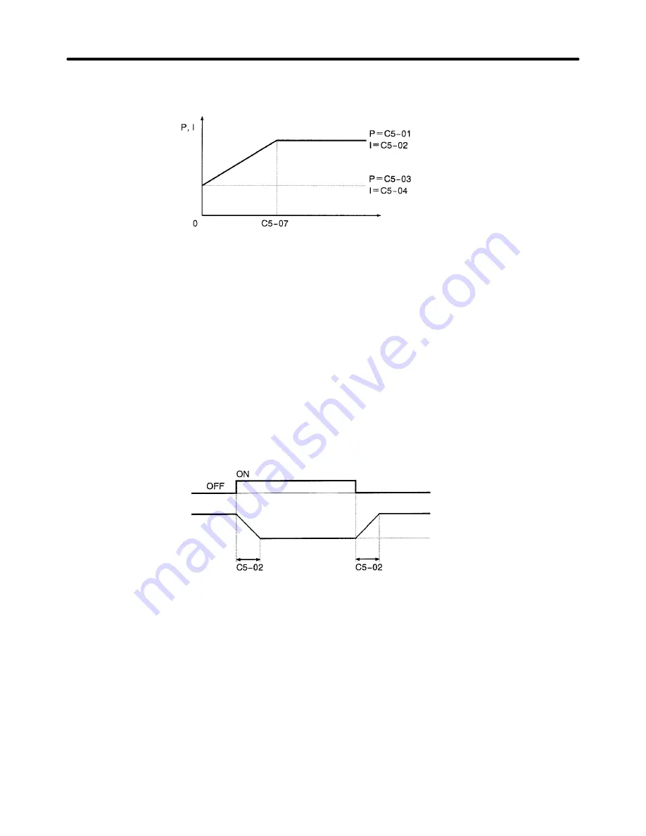
The following graph shows how the proportional gain and integral time approach ASR P Gain 2 and
ASR I Time 2 linearly as the frequency approaches zero.
Motor speed (Hz)
Note If C5-07 is set to 0.0, ASR P Gain 1 and ASR I Time 1 are used for the proportional gain and inte-
gral time at all frequencies.
H
Multi-function Input Settings (H1-01 through H1-06)
D
ASR Integral Reset (Setting E)
When one of the multi-function inputs is set to “E,” the input can be used to switch the speed control loop
between P control and PI control. P control (integral reset) is used when the multi-function input is ON.
D
ASR Proportional Gain Switch (Setting 77)
When one of the multi-function inputs is set to “77,” the input can be used to switch between proportional
gain 1 and proportional gain 2. Proportional gain 2 (C5-03) is used when the multi-function input is ON.
This input has higher priority than the ASR switching frequency set in C5-07.
ASR Gain Switch signal
(a multi-function input)
Proportional gain (P)
Proportional gain determined
by motor speed.
C5-03 gain setting
Note The gain is changed linearly in integral time 1 (C5-02). The integral time setting isn’t switched.
Basic Operation
Chapter 5
Summary of Contents for SYSDRIVE 3G3FV
Page 1: ...USER S MANUAL High function General purpose Inverter SYSDRIVE 3G3FV Cat No I516 E1 4 ...
Page 16: ...Chapter 1 Introduction 1 1 Function 1 2 Nomenclature 1 3 New Functions 1 ...
Page 33: ...Chapter 2 Installation 2 1 Mounting 2 2 Wiring 2 ...
Page 112: ...Chapter 4 Trial Operation 4 1 Procedure 4 2 Operation Example 4 ...
Page 289: ...Chapter 7 Parameter Lists 7 1 Initialize Mode Parameters 7 2 Program Mode Parameter List 7 ...
Page 366: ...Chapter 9 Specifications 9 1 Inverter Specifications 9 2 Option Specifications 9 ...
Page 395: ...Chapter 10 Appendix 10 1 Notes on Using the Inverter for a Motor 10 ...