ENGINE ELECTRICAL 6Y-25
MECHANICAL INSPECTION AND REPAIR
INSPECTION
In addition to the testing procedures for checking elec
trical circuits through various units, an inspection of all
parts should be made to determine their condition. Clean
all parts except bearing assemblies, which should not be
washed as they are packed with special lubricant.
1. Check drive end frame and bearing assembly for con
dition of bearing, felt seal, and retainer (fig. 8). Ex
amine end frame for cracks and for other damage.
2. Inspect rotor shaft rear bearing. If there is evidence
that bearing has been run without lubricant, or if
bearing is not in good condition, it must be replaced
as directed under “ Repair” later in this section.
3. Rotor assembly should be inspected for scoring at slip
rings (fig. 5). If shaft is damaged, a new rotor assem
bly should be installed at assembly. Procedure for re
surfacing slip rings is given later under “ Repair.”
4. Inspect brushes, brush springs, and brush holder. If
brushes are worn to half their original length or are
damaged they must be replaced. Visually inspect
brush springs; if springs are distorted, worn, or bro
ken, replace with new springs.
REPAIR
Drive End Frame Bearing Replacement (Fig. 8)
With generator disassembled into major components
proceed as follows to replace bearing assembly in drive
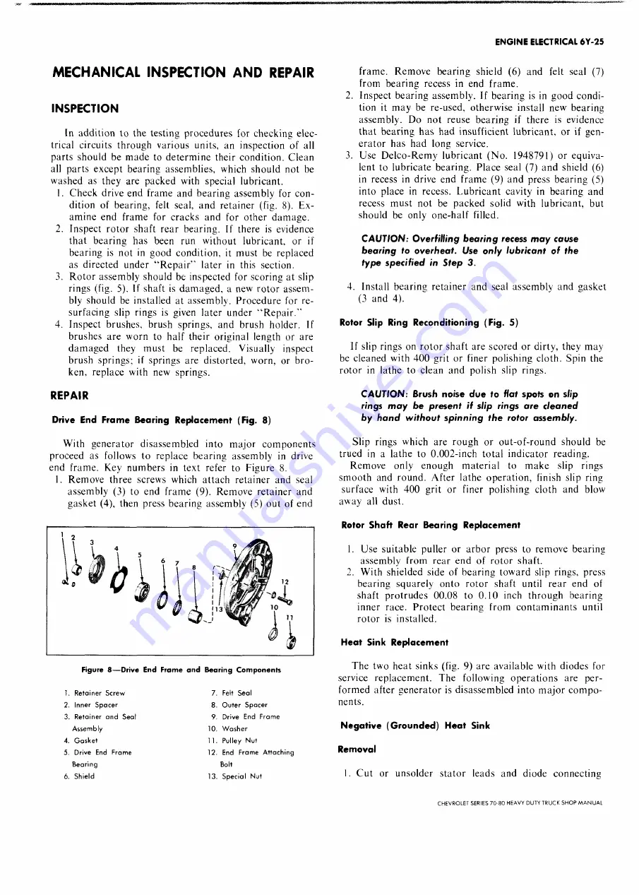
end frame. Key numbers in text refer to Figure 8.
1. Remove three screws which attach retainer and seal
assembly (3) to end frame (9). Remove retainer and
gasket (4), then press bearing assembly (5) out of end
F ig u re 8 — D riv e E n d F ra m e a n d B e a r in g C o m p o n e n t s
1. Retainer Screw
2. Inner Spacer
3. Retainer and Seal
Assembly
4. Gasket
5. Drive End Frame
Bearing
6. Shield
7. Felt Seal
8. Outer Spacer
9. Drive End Frame
10. Washer
11. Pulley Nut
12. End Frame Attaching
Bolt
13. Special Nut
frame. Remove bearing shield (6) and felt seal (7)
from bearing recess in end frame.
2. Inspect bearing assembly. If bearing is in good condi
tion it may be re-used, otherwise install new bearing
assembly. Do not reuse bearing if there is evidence
that bearing has had insufficient lubricant, or if gen
erator has had long service.
3. Use Delco-Remy lubricant (No. 1948791) or equiva
lent to lubricate bearing. Place seal (7) and shield (6)
in recess in drive end frame (9) and press bearing (5)
into place in recess. Lubricant cavity in bearing and
recess must not be packed solid with lubricant, but
should be only one-half filled.
CAUTIO N: O verfilling b e a rin g recess m a y cause
b e a rin g to overheat. Use o n ly lubricant of the
type specified in Step 3.
4. Install bearing retainer and seal assembly and gasket
(3 and 4).
Rotor Slip Ring Reconditioning (Fig. 5)
If slip rings on rotor shaft are scored or dirty, they may
be cleaned with 400 grit or finer polishing cloth. Spin the
rotor in lathe to clean and polish slip rings.
CAUTIO N: Brush noise due to Hat spots on slip
rings m a y be present it slip rings are cleaned
b y h a n d w ithout sp in n in g the rotor assem bly.
Slip rings which are rough or out-of-round should be
trued in a lathe to 0.002-inch total indicator reading.
Remove only enough material to make slip rings
smooth and round. After lathe operation, finish slip ring
surface with 400 grit or finer polishing cloth and blow
away all dust.
Rotor Shaft Rear Bearing Replacement
1. Use suitable puller or arbor press to remove bearing
assembly from rear end of rotor shaft.
2. With shielded side of bearing toward slip rings, press
bearing squarely onto rotor shaft until rear end of
shaft protrudes 00.08 to 0.10 inch through bearing
inner race. Protect bearing from contam inants until
rotor is installed.
Heat Sink Replacement
The two heat sinks (fig. 9) are available with diodes for
service replacement. The following operations are per
formed after generator is disassembled into major com po
nents.
Negative (Grounded) Heat Sink
Removal
I. Cut or unsolder stator leads and diode connecting
CHEVROLET SERIES 70-80 HEAVY DUTY TRUCK SH O P M A N U A L
Summary of Contents for 70 1969 Series
Page 1: ...CHEVROLET HEAVY DUTY TRUCK SHOP MANUAL...
Page 3: ......
Page 11: ...LUBRICATION 0 4 CHEVROLET SERIES 70 80 HEAVY DUTY TRUCK SHOP MANUAL...
Page 27: ......
Page 119: ......
Page 361: ......
Page 371: ......
Page 427: ......
Page 443: ......
Page 451: ......
Page 493: ......
Page 499: ......
Page 549: ......
Page 555: ......
Page 609: ......
Page 715: ...am...
Page 745: ......
Page 910: ......
Page 913: ......


