TRANSMISSION AND CLUTCH 7-127
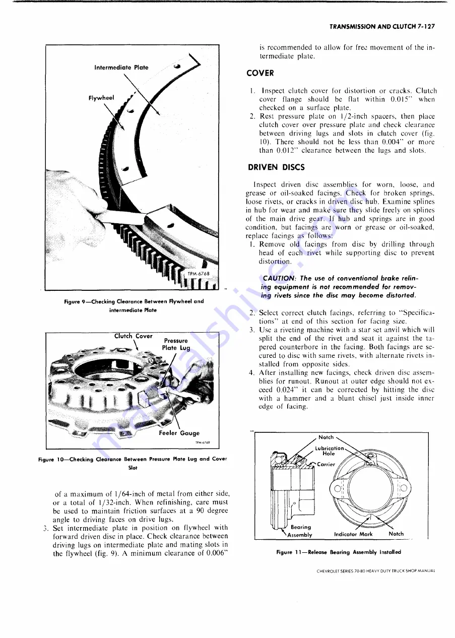
Interm ed ia te Plate
Flyw he el
is recom m ended to allow for free
term ediate plate.
m ovem ent of the in-
F ig u re 9 — C h e c k in g C le a ra n c e B e t w e e n F ly w h e e l a n d
in te rm e d ia te Plate
Pressure
P la te Lug
■
*
?! »
1-Or-
* . 4 T
— ------ i s I S -
F ig u re 1 0 — C h e c k in g C le a ra n c e B e t w e e n P re ssu re Plate L u g a n d C o v e r
Slot
of a m axim um of 1/64-inch of m etal from either side,
or a total of 1/32-inch. W hen refinishing, care must
be used to m aintain friction surfaces at a 90 degree
angle to driving faces on drive lugs.
Set interm ediate plate in position on flywheel with
forward driven disc in place. Check clearance between
driving lugs on interm ediate plate and m ating slots in
the flywheel (fig. 9). A m inim um clearance of 0.006”
COVER
1. Inspect clutch cover for distortion or cracks. Clutch
cover flange should be flat within 0.015” when
checked on a surface plate.
2. Rest pressure plate on l/2-inch spacers, then place
clutch cover over pressure plate and check clearance
between driving lugs and slots in clutch cover (fig.
10). There should not be less than 0.004” or more
than 0.012” clearance between the lugs and slots.
DRIVEN DISCS
Inspect driven disc assemblies for w'orn, loose, and
grease or oil-soaked facings. C heck for broken springs,
loose rivets, or cracks in driven disc hub. Exam ine splines
in hub for wear and m ake sure they slide freely on splines
of the main drive gear. If hub and springs are in good
condition, but facings are worn or grease or oil-soaked,
replace facings as follows:
1. Remove old facings from disc by drilling through
head of each rivet while supporting disc to prevent
distortion.
C A U T IO N : The use of con ven tional b rak e relin
in g e q u ip m e n t is not re co m m e n d e d for re m o v
in g rivets since the disc m a y becom e distorted.
2. Select correct clutch facings, referring to “ Specifica
tions” at end of this section for facing size.
3. Use a riveting m achine with a star set anvil which will
split the end of the rivet and seat it against the ta
pered counterbore in the facing. Both facings are se
cured to disc with sam e rivets, with alternate rivets in
stalled from opposite sides.
4. After installing new facings, check driven disc assem
blies for runout. R unout at outer edge should not ex
ceed 0.024” it can be corrected by hitting the disc
with a h am m er and a blunt chisel just inside inner
edge of facing.
F ig u re 1 1 — R e le a se B e a r in g A s s e m b ly In sta lle d
CHEVROLET SERIES 70-80 H EAVY DUTY TRUCK SH O P M A N U A L
Summary of Contents for 70 1969 Series
Page 1: ...CHEVROLET HEAVY DUTY TRUCK SHOP MANUAL...
Page 3: ......
Page 11: ...LUBRICATION 0 4 CHEVROLET SERIES 70 80 HEAVY DUTY TRUCK SHOP MANUAL...
Page 27: ......
Page 119: ......
Page 361: ......
Page 371: ......
Page 427: ......
Page 443: ......
Page 451: ......
Page 493: ......
Page 499: ......
Page 549: ......
Page 555: ......
Page 609: ......
Page 715: ...am...
Page 745: ......
Page 910: ......
Page 913: ......


