E N G IN E 6-12
center (No. 3) main bearing for evidence of wear where
they contact the sides of the bearing inserts. Measure
bearing journals with micrometer to determine if they are
out-of-round an to check the extent of wear. Use an accu
rate micrometer and check each journal at several points.
Check measurements against dimensions given in “ Speci
fications” at end of section. If bearing journals have been
ground undersize, subtract the am ount of undersize
(0.010, 0.020, 0.030 or 0.040 inch) from dimensions given,
to obtain the dimensions against which the measurements
should be checked. If not within specified limits for stan
dard or any of the undersize dimensions, crankshaft must
be ground to the next smaller undersize. (In the event the
crankshaft has been previously ground to smallest und
ersize and inspection reveals defective or worn bearing
journals, crankshaft must be replaced.)
G R IN D IN G C R A N K S H A F T
1. Use conventional type crankshaft grinder to correct
out-of-round of taper at crankshaft journals. Grind all
main bearing journals to com m on undersize and all
connecting rod journals to co m m on undersize.
2. Use grinding wheel dressed to provide fillet radius at
main bearing journals and fillet radius at connecting
rod journals. Refer to “ Specifications.” It is very im
portant to hold fillet dimensions within limits.
3. D i m e n s i o n s t o w h i c h c r a n k s h a f t j o u r n a l s an d
crankpins must be ground are determined by subtract
ing from the standard dimensions the am ount of und
ersize desired. Bearings are available in 0.002, 0.010,
0.020 and 0.030 inch undersize as well as standard
size.
4. After grinding journals, break sharp edges at oil holes
with small pencil type grinder.
5. When crankshaft main or connecting rod bearing
journals have been ground undersize, bearing halves
of same undersize must be obtained for assembly. If
crankshaft bearing journals are held within specified
limits when grinding, the undersize bearing halves will
provide the proper crankshaft-to-bearing clearance
when engine is assembled. Polish journals after grind
ing.
C R A N K S H A F T B E A R IN G IN S P E C T IO N
1. M ake a visual inspection of bearing halves for scor
ing, pitting, or other imperfections. If any dam age is
evident, new bearing halves must be used. A complete
set of new bearing halves should be used when re
placement is made. Never use a new bearing half with
a used one.
2. Using accurate-reading tube micrometer (fig. 15)
measure thickness of each bearing half at right angle
to split line. It is important to measure vertical thick
ness of each half of the bearing since the bearing
inner wall is not concentric with outer surface. Bear
ing wall thicknesses are given in “ Specifications" at
end of this section.
FLYWHEEL H O U S IN G A N D FLYWHEEL
H O U S IN G IN S P E C T IO N
Flywheel housings used with conventional transmissions
differ from housing used with autom atic transmissions,
hence the inspection procedure differs and procedures for
each type housing is covered separately under respective
headings below. Inspection to determine squareness of
rear face and concentricity of pilot hole must be made
after housing is installed on cylinder block.
1. Apron Type Housing Inspection
Check housing for damaged threads, and for cracked or
broken flanges. Bolt the housing to cylinder block and
check pilot hole for concentricity and rear face for
squareness with dial indicator mounted to crankshaft
flange or flywheel. Figures 16 and 17 show' typical use of
indicator. Housing should be replaced if bore an d /o r
transmission mounting face are not within tolerances
given in “ Specifications” listed at end of this section.
2. Two-Piece Type Housing
Inspect the flywheel housing and the clutch housing for
evidence of cracks an d /o r breakage.
To check for squareness at clutch housing rear face,
and for concentricity of pilot hole in clutch housing, re
move the clutch housing from transmission, referring to
T R A N S M I S S I O N (SEC. 7) for construction. M ount fly
wheel housing on engine and tighten mounting bolts to 50
to 60 foot-pounds torque. Be sure dowel pins (fig. 18) are
in place and in good condition.
Bolt clutch housing in place on flywheel housing, then
with dial indicator attached to crankshaft flange, check
for squareness at rear face of clutch housing as shown in
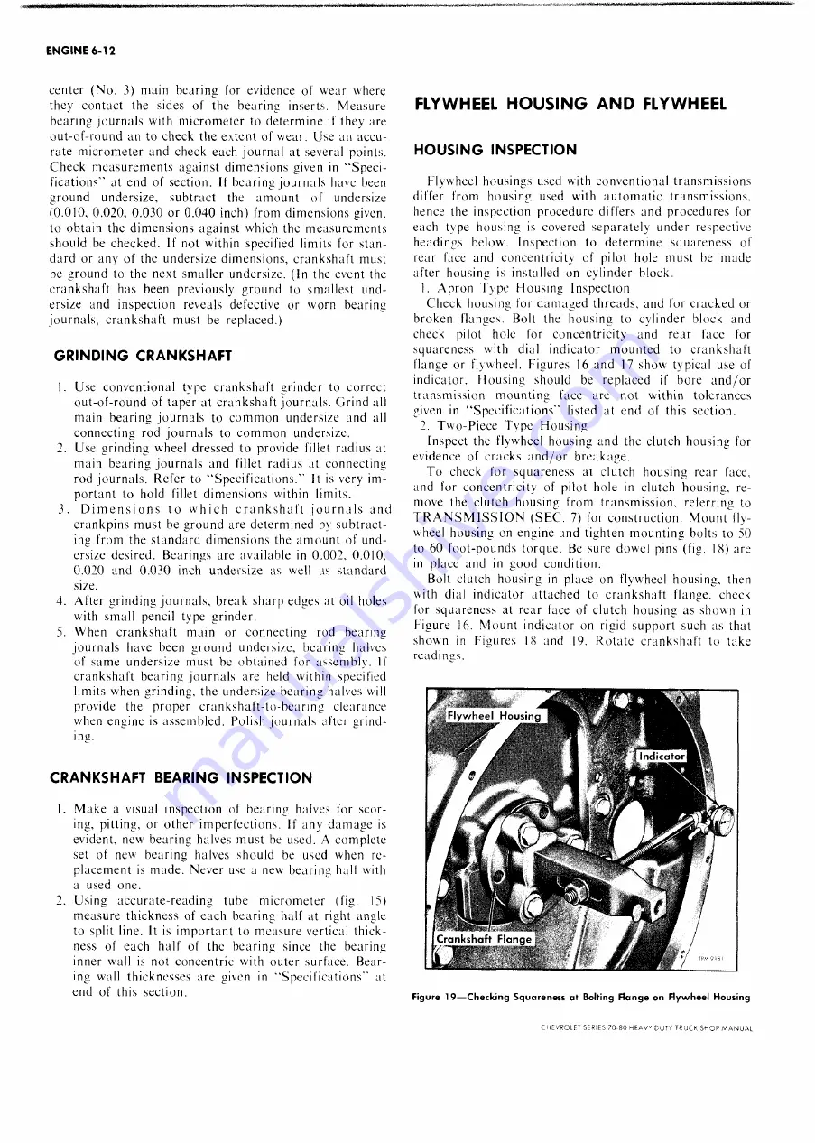
Figure 16. Mount indicator on rigid support such as that
shown in Figures 18 and 19. Rotate crankshaft to take
readings.
Figu re 1 9 — C h e c k in g S q u a r e n e ss a t Bolting F la n g e on Flyw h eel H o u sin g
CHEVROLFT SERIES 70-80 H E A V V DUTY TRUCK S H O P M A N U A L
Summary of Contents for 70 1969 Series
Page 1: ...CHEVROLET HEAVY DUTY TRUCK SHOP MANUAL...
Page 3: ......
Page 11: ...LUBRICATION 0 4 CHEVROLET SERIES 70 80 HEAVY DUTY TRUCK SHOP MANUAL...
Page 27: ......
Page 119: ......
Page 361: ......
Page 371: ......
Page 427: ......
Page 443: ......
Page 451: ......
Page 493: ......
Page 499: ......
Page 549: ......
Page 555: ......
Page 609: ......
Page 715: ...am...
Page 745: ......
Page 910: ......
Page 913: ......


