AIR COMPRESSORS AND GOVERNORS 6T-4
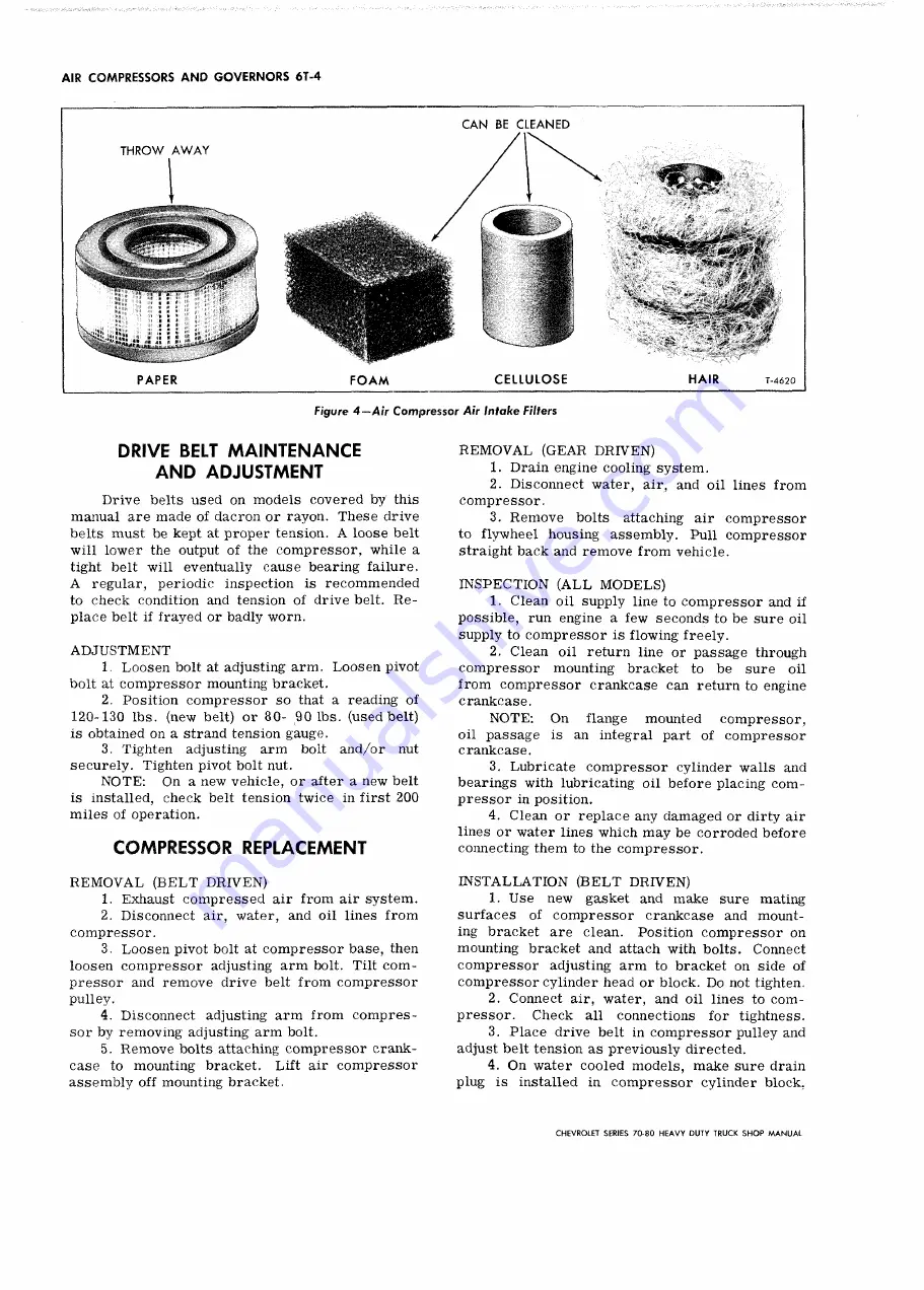
Figure 4 — Air Compressor Air Intake Filters
DRIVE BELT MAINTENANCE
AND ADJUSTMENT
Drive belts used on models covered by this
manual are made of dacron or rayon. These drive
belts must be kept at proper tension. A loose belt
will lower the output of the compressor, while a
tight belt will eventually cause bearing failure.
A regular, periodic inspection is recommended
to check condition and tension of drive belt. R e
place belt if frayed or badly worn.
A D J U S T M E N T
1. Loosen bolt at adjusting arm. Loosen pivot
bolt at compressor mounting bracket.
2. Position compressor so that a reading of
120-130 lbs. (new belt) or 80- 90 lbs. (used belt)
is obtained on a strand tension gauge.
3. Tighten adjusting arm bolt and/or nut
securely. Tighten pivot bolt nut.
N O T E :
On a new vehicle, or after a new belt
is installed, check belt tension twice in first 200
miles of operation.
COMPRESSOR REPLACEMENT
R E M O V A L (B E L T D RIVEN )
1. Exhaust compressed air from air system.
2. Disconnect air, water, and oil lines from
compressor.
3. Loosen pivot bolt at compressor base, then
loosen compressor adjusting arm bolt. Tilt com
pressor and remove drive belt from compressor
pulley.
4. Disconnect adjusting arm from compres
sor by removing adjusting arm bolt.
5. Remove bolts attaching compressor crank
case to mounting bracket. Lift air compressor
assembly off mounting bracket.
R E M O V A L (G EA R DRIVEN)
1. Drain engine cooling system.
2. Disconnect water, air, and oil lines from
compressor.
3. Remove bolts attaching air compressor
to flywheel housing assembly. Pull compressor
straight back and remove from vehicle.
IN SP E C T IO N (A L L M O D E L S )
1. Clean oil supply line to compressor and if
possible, run engine a few seconds to be sure oil
supply to compressor is flowing freely.
2. Clean oil return line or passage through
compressor mounting bracket to be sure oil
from compressor crankcase can return to engine
crankcase.
N O T E :
On
flange
mounted
compressor,
oil passage is an integral part of compressor
crankcase.
3. Lubricate compressor cylinder walls and
bearings with lubricating oil before placing com
pressor in position.
4. Clean or replace any damaged or dirty air
lines or water lines which may be corroded before
connecting them to the compressor.
IN S T A L L A T IO N (B E L T DRIVEN )
1. Use new gasket and make sure mating
surfaces of compressor crankcase and mount
ing bracket are clean. Position compressor on
mounting bracket and attach with bolts. Connect
compressor adjusting arm to bracket on side of
compressor cylinder head or block. Do not tighten.
2. Connect air, water, and oil lines to com
pressor.
Check all connections for tightness.
3. Place drive belt in compressor pulley and
adjust belt tension as previously directed.
4. On water cooled models, make sure drain
plug is installed in compressor cylinder block.
CHEVROLET SERIES 70-80 H EAVY DUTY TRUCK SH O P M A N U A L
Summary of Contents for 70 1969 Series
Page 1: ...CHEVROLET HEAVY DUTY TRUCK SHOP MANUAL...
Page 3: ......
Page 11: ...LUBRICATION 0 4 CHEVROLET SERIES 70 80 HEAVY DUTY TRUCK SHOP MANUAL...
Page 27: ......
Page 119: ......
Page 361: ......
Page 371: ......
Page 427: ......
Page 443: ......
Page 451: ......
Page 493: ......
Page 499: ......
Page 549: ......
Page 555: ......
Page 609: ......
Page 715: ...am...
Page 745: ......
Page 910: ......
Page 913: ......


