REAR SUSPENSION 4A-16
21, 22, and 23. Reference will be made to those
illustrations during the following disassembly oper
ations, and also in the assembly operations.
1. Remove three screws and lockwashers (16)
which attach bearing cover (15) to bottom of shift
unit housing. Remove cover and gasket (14).
2. Push down on drive screw assembly (20)
until bearing assembly (12) is free of housing.
3. Insert screwdriver in drive slot of screw
(fig. 20); then remove bearing lock nut (13) and
bearing with snap ring (12). Drive screw assembly
(20) can then be lifted out of housing.
4. Remove the two lock nuts (19) from switch
terminals (17). Pull off motor wires (fig. 21).
5. Remove three screws and lock washers (1)
which attach motor cover (4) to housing. Pull out
motor (6) with cover (4) attached to motor (fig. 22),
with two cover nuts (2). Grommet (7) can then be
removed.
6. Remove two jam nuts (9) and fiber washers
(10) from outside of housing. On inside remove
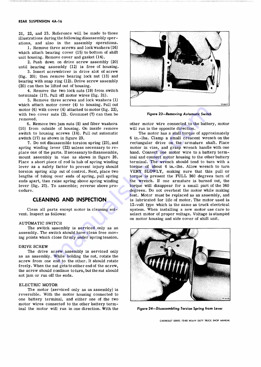
switch to housing screws (18). Pull out automatic
switch (17) as shown in figure 23.
7. Do not disassemble torsion spring (23), and
spring winding lever (22) unless necessary to re
place one of the parts. If necessary to disassemble,
mount assembly in vise as shown in figure 26.
Place a short piece of rod in hub of spring winding
lever as a safety factor to prevent injury should
torsion spring slip out of control. Next, place two
lengths of tubing over ends of spring, pull spring
ends apart, then raise spring above spring winding
lever (fig. 27). To assemble; reverse above pro
cedure.
CLEANING AN D INSPECTION
Clean all parts except motor in cleaning sol
vent. Inspect as follows:
A U T O M A T IC S W IT C H
The switch assembly is serviced only as an
assembly. The switch should have clean free mov
ing points which close firmly under spring tension.
D R IV E S C R E W
The drive screw assembly is serviced only
as an assembly. While holding the nut, rotate the
screw from one end to the other. It should rotate
freely. When the nut gets to either end of the screw,
the screw should continue to turn, but the nut should
not jam or run off the ends.
E L E C T R IC M O T O R
The motor (serviced only as an assembly) is
reversible. With the motor housing connected to
one battery terminal, and either one of the two
motor wires connected to the other battery term
inal the motor will run in one direction. With the
Figure 2 3 — Removing Automatic Switch
other motor wire connected to the battery, motor
will run in the opposite direction.
The motor has a stall torque of approximately
6 in.-lbs. Clamp a small crescent wrench on the
rectangular drive on the armature shaft. Place
motor in vise, and grasp wrench handle with one
hand. Connect one motor wire to a battery term
inal and connect motor housing to the other battery
terminal. The wrench should tend to turn with a
torque of about 6 in.-lbs. Allow wrench to turn
V E R Y S L O W L Y , making sure that this pull or
torque is present the F U L L 360 degrees turn of
the wrench. If one armature is burned out, the
torque will disappear for a small part of the 360
degrees. Do not overheat the motor while making
test. Motor must be replaced as an assembly, and
is lubricated for life of motor. The motor used is
12-volt type which is the same as truck electrical
system. When installing a new motor use care to
select motor of proper voltage. Voltage is stamped
on motor housing and side cover of shift unit.
Figure 24— Disassembling Torsion Spring from Lever
CHEVROLET SERIES 70-80 H EAVY DUTY TRUCK S H O P M A N U A L
Summary of Contents for 70 1969 Series
Page 1: ...CHEVROLET HEAVY DUTY TRUCK SHOP MANUAL...
Page 3: ......
Page 11: ...LUBRICATION 0 4 CHEVROLET SERIES 70 80 HEAVY DUTY TRUCK SHOP MANUAL...
Page 27: ......
Page 119: ......
Page 361: ......
Page 371: ......
Page 427: ......
Page 443: ......
Page 451: ......
Page 493: ......
Page 499: ......
Page 549: ......
Page 555: ......
Page 609: ......
Page 715: ...am...
Page 745: ......
Page 910: ......
Page 913: ......


