POWER BRAKE 5-41
Figure 16 — V ie w o f O ffse t C o n n e c tin g Rod (L o n g Boss)
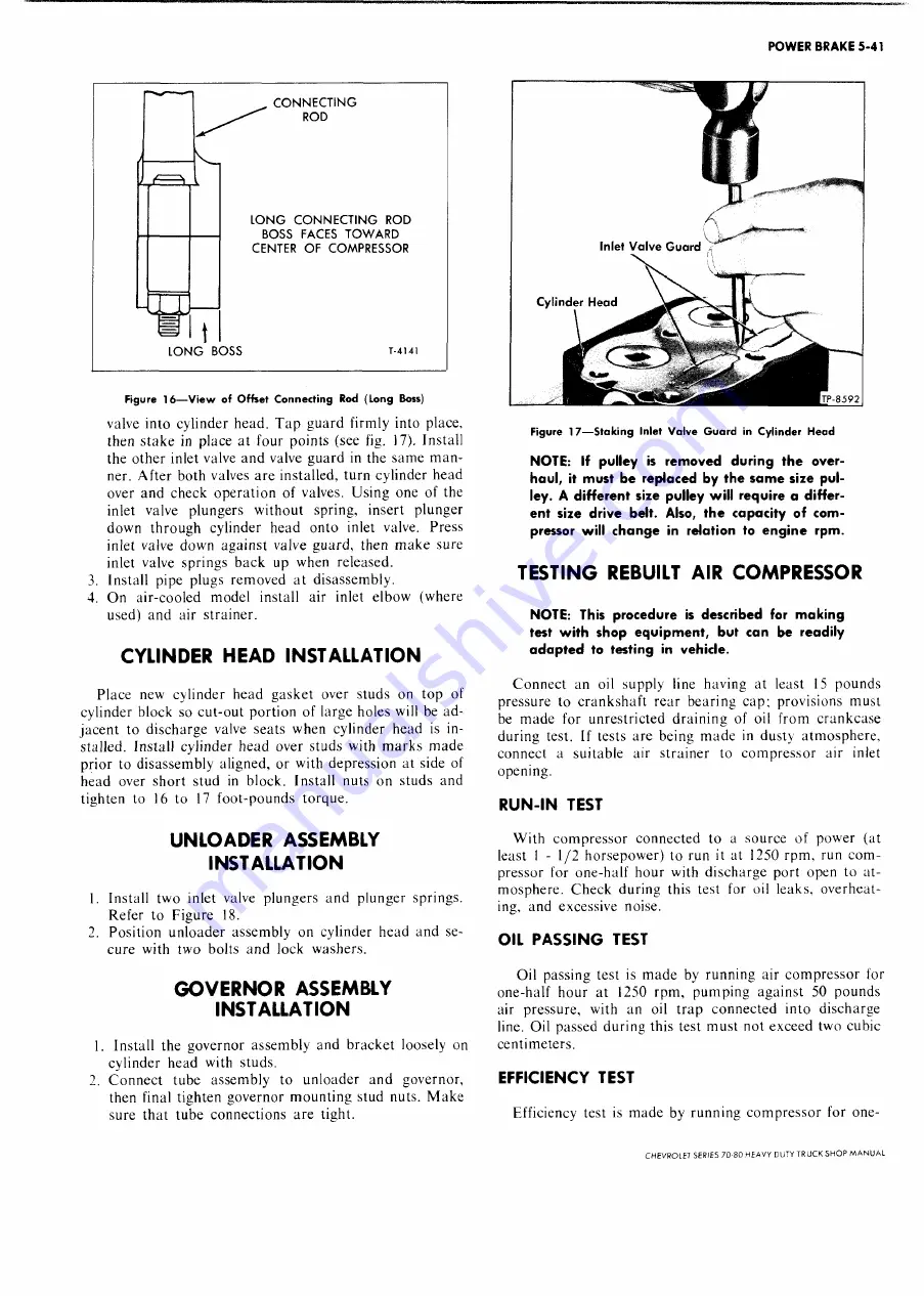
valve into cylinder head. T ap guard firmly into place,
then stake in place at four points (see fig. 17). Install
the other inlet valve and valve guard in the sam e m a n
ner. After both valves are installed, turn cylinder head
over and check operation of valves. Using one of the
inlet valve plungers w ithout spring, insert plunger
down through cylinder head onto inlet valve. Press
inlet valve down against valve guard, then m ake sure
inlet valve springs back up when released.
3. Install pipe plugs removed at disassembly.
4. O n air-cooled model install air inlet elbow (where
used) and air strainer.
CYLINDER HEAD INSTALLATION
Place new cylinder head gasket over studs on top of
cylinder block so cut-out portion of large holes will be ad
jacent to discharge valve seats when cylinder head is in
stalled. Install cylinder head over studs with m arks m ade
prior to disassembly aligned, or with depression at side of
head over short stud in block. Install nuts on studs and
tighten to 16 to 17 foot-pounds torque.
UNLOADER ASSEMBLY
INSTALLATION
1. Install two inlet valve plungers and plunger springs.
Refer to Figure 18.
2. Position unloader assembly on cylinder head and se
cure with two bolts and lock washers.
G O V ERN O R ASSEMBLY
INSTALLATION
1. Install the governor assembly and bracket loosely on
cylinder head with studs.
2. C onnect tube assembly to unloader and governor,
then final tighten governor m ounting stud nuts. M ake
sure that tube connections are tight.
A
Inlet Valve Guard
V
I i
Figure 1 7 — S t a k in g Inlet V a lv e G u a r d in C y lin d e r H e a d
NOTE: If pulley is removed during the over
haul, it must be replaced by the same size pul
ley. A different size pulley will require a differ
ent size drive belt. Also, the capacity of com
pressor will change in relation to engine rpm.
TESTING REBUILT AIR CO M PRESSOR
NOTE: This procedure is described for making
test with shop equipment, but can be readily
adapted to testing in vehicle.
C onnect an oil supply line having at least 15 pounds
pressure to crankshaft rear bearing cap; provisions must
be m ade for unrestricted draining of oil from crankcase
during test. If tests are being m ade in dusty atm osphere,
connect a suitable air strainer to com pressor air inlet
opening.
RUN-IN TEST
W ith com pressor connected to a source of power (at
least 1 - 1 / 2 horsepower) to run it at 1250 rpm , run com
pressor for one-half hour with discharge port open to at
mosphere. Check during this test for oil leaks, overheat
ing, and excessive noise.
OIL PASSING TEST
Oil
passing test is m ade by running air com pressor for
one-half hour at 1250 rpm, pum ping against 50 pounds
air pressure, with an oil trap connected into discharge
line. Oil passed during this test m ust not exceed two cubic
centimeters.
EFFICIENCY TEST
Efficiency test is m ade by running com pressor for one-
CHEVROLET SERIES 70-80 HEAVY DUTY TRUCK SH O P M A N UA L
Summary of Contents for 70 1969 Series
Page 1: ...CHEVROLET HEAVY DUTY TRUCK SHOP MANUAL...
Page 3: ......
Page 11: ...LUBRICATION 0 4 CHEVROLET SERIES 70 80 HEAVY DUTY TRUCK SHOP MANUAL...
Page 27: ......
Page 119: ......
Page 361: ......
Page 371: ......
Page 427: ......
Page 443: ......
Page 451: ......
Page 493: ......
Page 499: ......
Page 549: ......
Page 555: ......
Page 609: ......
Page 715: ...am...
Page 745: ......
Page 910: ......
Page 913: ......


