FUEL TANK AND EXHAUST 8A-2
termine actual source of leak. "Seam leaks" often
turn out to be leaks at filler neck, fuel line con
nections, or at tank sendingunit seal. In such cases,
fuel runs down side of tank to flanges and drips off
at points along the seam giving a false indication
of leaking seams. If careful inspection reveals that
tank is actual source of leaks, then remove tank,
for repairs as required.
IM P O R T A N T : A leaking fuel tank must be re
paired or replaced immediately. In addition to in
creased operating expense, leaking fuel tanks
represent a serious fire hazard. No leakage is
permissible anywhere in fuel system lines or tank(s).
FUEL LINE INSTALLATION
In making up fuel lines, it is important that
the ends of the tubing be flared properly for toe
compression couplings. Unless the tubing is prop
erly flared, the couplings will leak.
The tubing must be double-lap flared at the
ends in order to produce a strong leak-proof joint.
The Tool J-8051 (fig. 2) must be equipped
with the proper size die block and upset flare
punch for each size tubing to form the double-lap
flare.
The proper size die blocks and upset flare
punches are as follows:
Tubing
Size
3 /1 6 "
1 /4 "
5 /1 6 "
Die Block
J-2185-27
J-2185-28
J-2185-29
Upset
Flare Punch
J-2185-3
J-2185-37
J-2185-4
Finish
Flare Punch
J-2185-26
J-2185-26
J-2185-26
N O T E :
These special tools are also part of
Kit J-8051.
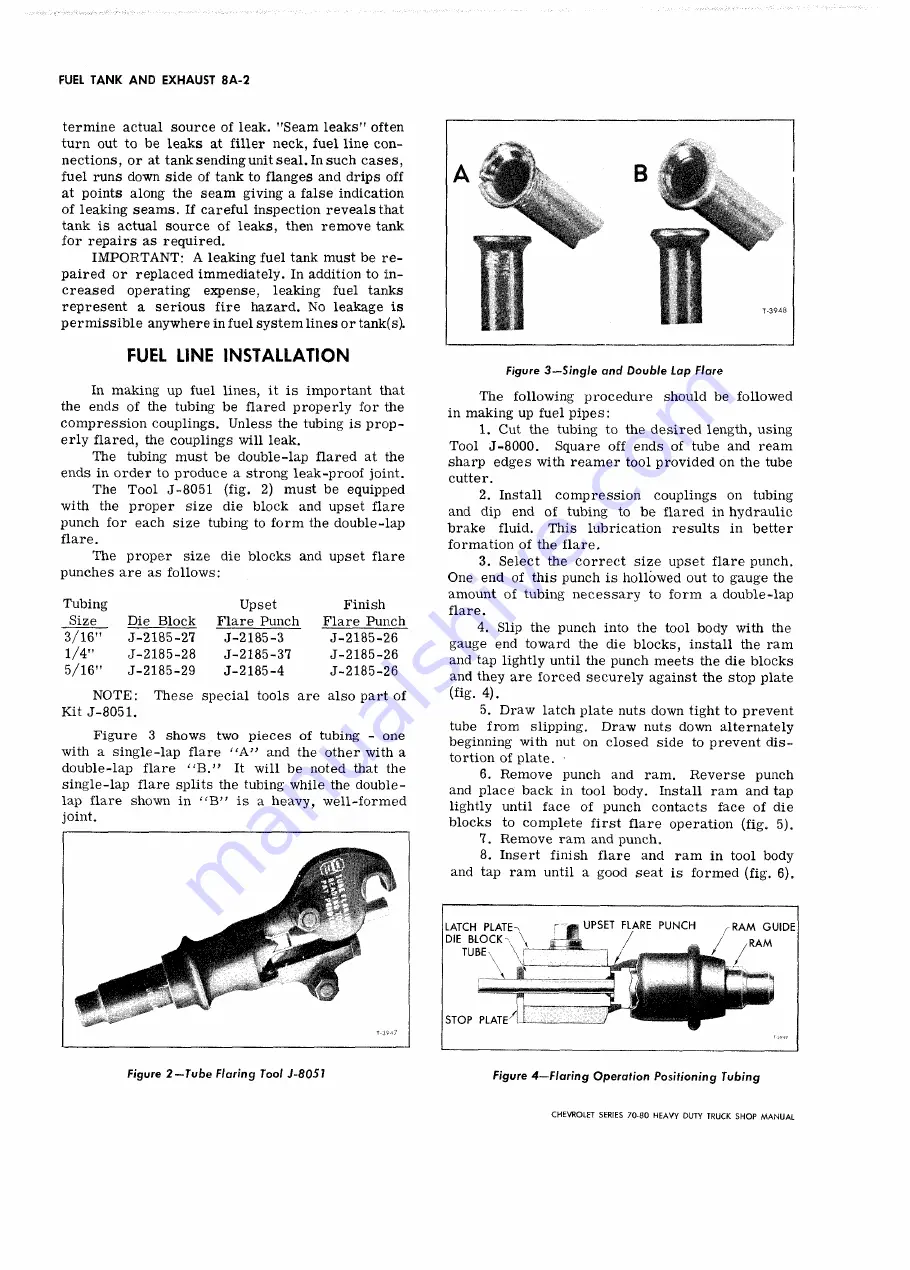
Figure 3 shows two pieces of tubing - one
with a single-lap flare
“ A ”
and the other with a
double-lap flare “ B .” It will be noted that the
single-lap flare splits the tubing while the double-
lap flare shown in
is a heavy, well-formed
joint.
i l
Figure
3-~Single and Double Lap Flare
The following procedure should be followed
in making up fuel pipes:
1. Cut the tubing to the desired length, using
Tool J-8000.
Square off ends of tube and ream
sharp edges with reamer tool provided on the tube
cutter.
2. Install compression couplings on tubing
and dip end of tubing to be flared in hydraulic
brake fluid. This lubrication results in better
formation of the flare.
3. Select the correct size upset flare punch.
One end of this punch is hollowed out to gauge the
amount of tubing necessary to form a double-lap
flare.
4. Slip the punch into the tool body with the
gauge end toward the die blocks, install the ram
and tap lightly until the punch meets the die blocks
and they are forced securely against the stop plate
(fig. 4).
5. Draw latch plate nuts down tight to prevent
tube from slipping. Draw nuts down alternately
beginning with nut on closed side to prevent dis
tortion of plate.
6. Remove punch and ram. Reverse punch
and place back in tool body. Install ram and tap
lightly until face of punch contacts face of die
blocks to complete first flare operation (fig. 5).
1. Remove ram and punch.
8. Insert finish flare and ram in tool body
and tap ram until a good seat is formed (fig. 6).
LATCH PLATE-
n
DIE B L O C K
,
T U B E \
'• ■-
t
S T O P PLATE
Figure 2 — Tube Flaring Tool J-8051
Figure 4— Flaring Operation Positioning Tubing
CHEVROLET SERIES 70 -80 H EAVY DUTY TRUCK SH O P M A N U A L
Summary of Contents for 70 1969 Series
Page 1: ...CHEVROLET HEAVY DUTY TRUCK SHOP MANUAL...
Page 3: ......
Page 11: ...LUBRICATION 0 4 CHEVROLET SERIES 70 80 HEAVY DUTY TRUCK SHOP MANUAL...
Page 27: ......
Page 119: ......
Page 361: ......
Page 371: ......
Page 427: ......
Page 443: ......
Page 451: ......
Page 493: ......
Page 499: ......
Page 549: ......
Page 555: ......
Page 609: ......
Page 715: ...am...
Page 745: ......
Page 910: ......
Page 913: ......


