BRAKES 5B-27
enough it can result in slow brake release. If stop
screw is not turned down far enough, excessive
pedal travel will be required to start the brake ap
plication, and full application may not be obtained.
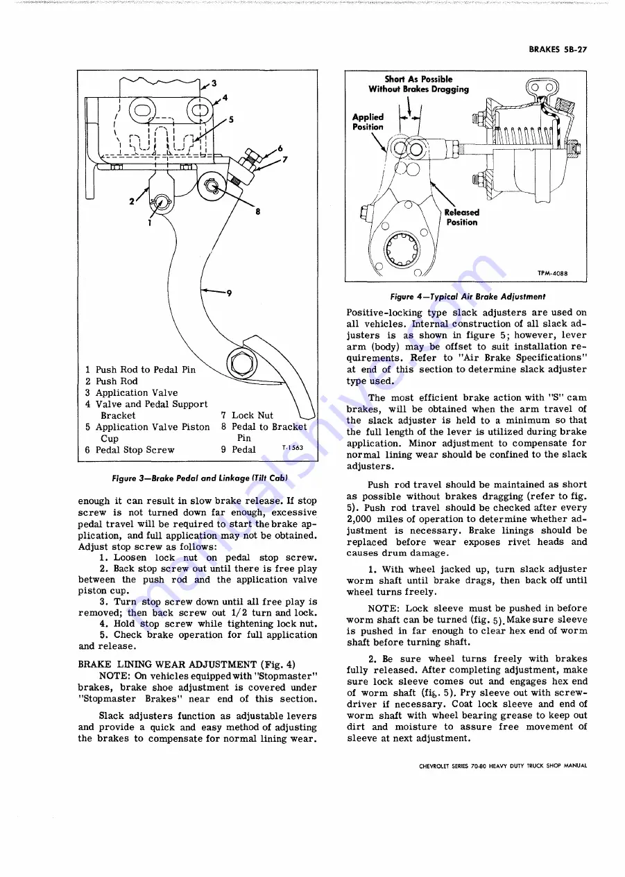
Adjust stop screw as follows:
1. Loosen lock nut on pedal stop screw.
2. Back stop screw out until there is free play
between the push rod and the application valve
piston cup.
3. Turn stop screw down until all free play is
removed; then back screw out 1/2 turn and lock.
4. Hold stop screw while tightening lock nut.
5. Check brake operation for full application
and release.
B R A KE LINING W E A R A D J U S T M E N T (Fig. 4)
N O T E : On vehicles equipped with "Stopmaster"
brakes, brake shoe adjustment is covered under
"Stopmaster Brakes" near end of this section.
Slack adjusters function as adjustable levers
and provide a quick and easy method of adjusting
the brakes to compensate for normal lining wear.
Figure 4 — Typical Air Brake Adjustment
Positive-locking type slack adjusters are used on
all vehicles. Internal construction of all slack ad
justers is as shown in figure 5; however, lever
arm (body) may be offset to suit installation re
quirements. Refer to "Air Brake Specifications”
at end of this section to determine slack adjuster
type used.
The most efficient brake action with "S " cam
brakes, will be obtained when the arm travel of
the slack adjuster is held to a minimum so that
the full length of the lever is utilized during brake
application. Minor adjustment to compensate for
normal lining wear should be confined to the slack
adjusters.
Push rod travel should be maintained as short
as possible without brakes dragging (refer to fig.
5). Push rod travel should be checked after every
2,000 miles of operation to determine whether ad
justment is necessary. Brake linings should be
replaced before wear exposes rivet heads and
causes drum damage.
1. With wheel jacked up, turn slack adjuster
worm shaft until brake drags, then back off until
wheel turns freely.
N O T E : Lock sleeve must be pushed in before
w orm shaft can be turned (fig. 5). Make sure sleeve
is pushed in far enough to clear hex end of worm
shaft before turning shaft.
2. Be sure wheel turns freely with brakes
fully released. After completing adjustment, make
sure lock sleeve comes out and engages hex end
of worm shaft (fig. 5). Pry sleeve out with screw
driver if necessary. Coat lock sleeve and end of
worm shaft with wheel bearing grease to keep out
dirt and moisture to assure free movement of
sleeve at next adjustment.
CHEVROLET SERIES 70 -80 H EAVY DUTY TRUCK SH O P M A N U A L
Summary of Contents for 70 1969 Series
Page 1: ...CHEVROLET HEAVY DUTY TRUCK SHOP MANUAL...
Page 3: ......
Page 11: ...LUBRICATION 0 4 CHEVROLET SERIES 70 80 HEAVY DUTY TRUCK SHOP MANUAL...
Page 27: ......
Page 119: ......
Page 361: ......
Page 371: ......
Page 427: ......
Page 443: ......
Page 451: ......
Page 493: ......
Page 499: ......
Page 549: ......
Page 555: ......
Page 609: ......
Page 715: ...am...
Page 745: ......
Page 910: ......
Page 913: ......


