ENGINE C O O L IN G SYSTEM 6K-11
A S S E M B L Y (Refer to Fig. 9)
1. Clean all parts in solvent and wipe dry.
Check bearings for damage, wear and roughness.
Replace bearing if found defective in any way.
2. Using a suitable size sleeve, tap bearing
cups and grease baffle into position in pulley.
3. Use grade No. 2 lithium base, multi-purpose
grease and pressure lubricate bearings. Fill fan
hub cap to 3/4 full. Take 1/2 of grease from hub
cap and pack into cavity between grease baffle and
rear bearing cup. Refill hub cap to 3/4 full.
4. Insert rear bearing assembly into position
in pulley and tap seal into place in pulley.
5. Install pulley on shaft and insert bearing
spacer into pulley. Position shims against bearing
spacer and install front bearing assembly.
N O T E : Three different size shims are avail
able and the thickness of each is identified by
notches on the shim as follows:
No notches - 0.015 inch
1 notch
- 0.020 inch
2 notches
- 0.025 inch
6. Install flat washer and bolt. While rotating
pulley, tighten bolt to 85 to 95 foot-pounds torque.
7. Check end play of pulley with dial indicator.
End play must be between 0.001 and 0.006-inch.
8. If end play is not correct, remove bolt,
washer and front bearing assembly. Arrange shims
to give correct end play (identify shims as noted
in Step 5).
9. Install front bearing assembly and repeat
Steps 6 and 7. After proper end play is obtained,
tap fan hub cap into position on pulley.
IN S T A L L A T IO N
1. Place support and adjustment assembly in
its original position on the engine.
2. Start four adjusting bracket locking bolts.
3. Install drive belts on pulley and install ad
justing bolt in adjusting bracket.
4. Turn adjusting bolt until belt tension of 120
to 130 pounds (using tension gauge) is achieved (90
to 100 pounds for used belt). Tighten locking bolts.
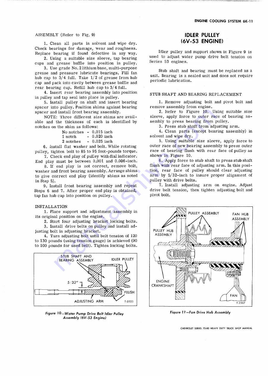
Figure 10
—Water Pump Drive Belt Idler Pulley
Assembly 16V-53 Engine)
IDLER PULLEY
(6V-53 ENGINE)
Idler pulley and support shown in Figure 9 is
used to adjust water pump drive belt tension on
Series 53 engines.
Stub shaft and bearing must be replaced as a
unit. Bearing is a sealed unit and does not require
periodic lubrication.
STUB S H A F T A N D BEARIN G R E P L A C E M E N T
1. Remove adjusting bolt and pivot bolt and
remove assembly from engine.
2. Refer to Figure 10. Using suitable size
sleeve, apply force to outer race of bearing as
sembly to press bearing from pulley.
3. Press stub shaft from adjusting arm.
4. Clean parts (except bearing assembly) in
solvent and wipe dry.
5. Using suitable size sleeve, apply force to
outer race of new bearing assembly to press outer
race of bearing flush with rear face of pulley as
shown in Figure 10.
6. Apply force to stub shaft to press stub shaft
flush with rear face of adjusting arm. In this posi
tion, rear face of pulley should clear adjusting
arm by 5 / 32-inch to insure proper alignment of
pulley with drive belts.
7. Install adjusting arm on engine. Adjust
drive belt tension, then tighten adjusting bolt and
pivot bolt.
CHEVROLET SERIES 70-80 H EAVY DUTY TRUCK SH O P M A N U A L
Summary of Contents for 70 1969 Series
Page 1: ...CHEVROLET HEAVY DUTY TRUCK SHOP MANUAL...
Page 3: ......
Page 11: ...LUBRICATION 0 4 CHEVROLET SERIES 70 80 HEAVY DUTY TRUCK SHOP MANUAL...
Page 27: ......
Page 119: ......
Page 361: ......
Page 371: ......
Page 427: ......
Page 443: ......
Page 451: ......
Page 493: ......
Page 499: ......
Page 549: ......
Page 555: ......
Page 609: ......
Page 715: ...am...
Page 745: ......
Page 910: ......
Page 913: ......


