E N G IN E 6-22
in cylinder head as shown in Figure 32. Press tool
firmly against ring, then while holding tool with
handle, tighten screw to expand tool which will
engage inner edge of ring.
b. Insert driver through valve guide and into contact
with tool. Strike driver sharply to drive ring out of
counterbore in cylinder head. If preferred, a slide
ham m er may be attached to threaded end of seat
remover for use instead of driver shown in Figure
32.
c. Be sure that cylinder head is clean, particularly the
counterbore for inserts.
d. Pack new inserts in dry ice for a minim um of 15
minutes.
e. Preheat cylinder head by immersion in water at a
temperature of 180 degrees F. to 200 degrees F.
Place cylinder head on bench, blow out each insert
counterbore with air, then lay chilled insert in
counterbore with valve side toward installer.
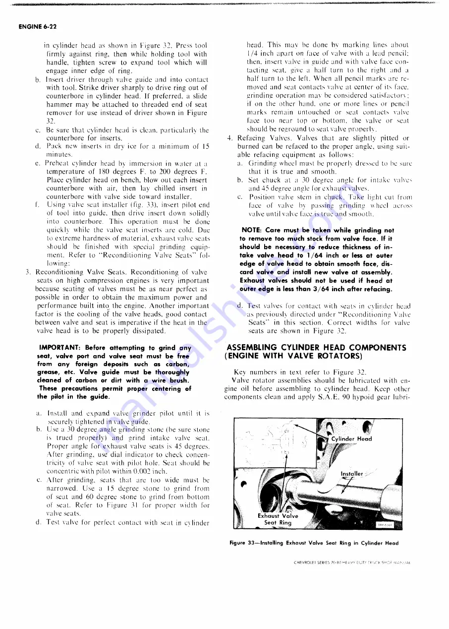
f. Using valve seat installer (fig. 33), insert pilot end
of tool into guide, then drive insert down solidly
into counterbore. This operation must be done
quickly while the valve seat inserts are cold. Due
to extreme hardness of material, exhaust valve seats
should be finished with special grinding equip
ment. Refer to “ Reconditioning Valve Seats" fol
lowing:
3. Reconditioning Valve Seats. Reconditioning of valve
seats on high compression engines is very important
because seating of valves must be as near perfect as
possible in order to obtain the m axim um power and
performance built into the engine. Another important
factor is the cooling of the valve heads, good contact
between valve and seat is imperative if the heat in the
valve head is to be properly dissipated.
IMPORTANT: Before attempting to grind any
seat, valve port and valve seat must be free
from any foreign deposits such as carbon,
grease, etc. Valve guide must be thoroughly
cleaned of carbon or dirt with a wire brush.
These precautions permit proper centering of
the pilot in the guide.
a. Install and expand valve grinder pilot until it is
securely tightened in valve guide.
b. Use a 30 degree angle grinding stone (be sure stone
is trued properly) and grind intake valve seat.
Proper angle for exhaust valve seats is 45 degrees.
After grinding, use dial indicator to check concen
tricity of valve seat with pilot hole. Seat should be
concentric with pilot within 0.002 inch.
e. After grinding, seats that are too wide must be
narrowed. Use a 15 degree stone to grind from
of seat and 60 degree stone to grind from bottom
of seat. Refer to Figure 31 for proper width for
valve seats.
d. Test valve for perfect contact with seat in cylinder
head. This may be done by m arking lines about
1/4 inch apart on face of valve with a lead pencil:
then, insert valve in guide and with valve face con
tacting seat, give a half turn to the right and a
half turn to the left. When all pencil marks are re
moved and seat contacts valve at center of its face,
grinding operation mav be considered satisfaclorx;
if on the other hand, one or more lines or pencil
m arks remain untouched or seat contacts valve
face too near top or bottom, the valve or seat
should be reground to seat valve properly.
4. Refacing Valves. Valves that are slightly pitted or
burned can be refaced to the proper angle, using suit
able refacing equipment as follows:
a. Grinding wheel must be properly dressed to be sure
that it is true and smooth.
b. Set chuck at a 30 degree angle for intake valves
and 45 degree angle for exhaust valves.
c. Position valve stem in chuck. Take light cut from
face of valve by passing grinding wheel across
valve until valve face is true and smooth.
NOTE: Care must be taken while grinding not
to remove too much stock from valve face. If it
should be necessary to reduce thickness of in
take valve head to 1/64 inch or less at outer
edge of valve head to obtain smooth face, dis
card valve and install new valve at assembly.
Exhaust valves should not be used if head at
outer edge is less than 3/64 inch after refacing.
d. Test valves for contact with seats in cylinder head
as previously directed under “ Reconditioning Valve
Seats" in this section. Correct widths for valve
seats are shown in Figure 32.
ASSEMBLING CYLINDER HEAD COMPONENTS
(ENGINE WITH VALVE ROTATORS)
Key numbers in text refer to Figure 32.
Valve rotator assemblies should be lubricated with en
gine oil before assembling to cylinder head. Keep other
components clean and apply S.A.E. 90 hypoid gear lubri-
CHEVROLET SF R 'E S 70-80 u F A Vv r-urv
S 'J
Summary of Contents for 70 1969 Series
Page 1: ...CHEVROLET HEAVY DUTY TRUCK SHOP MANUAL...
Page 3: ......
Page 11: ...LUBRICATION 0 4 CHEVROLET SERIES 70 80 HEAVY DUTY TRUCK SHOP MANUAL...
Page 27: ......
Page 119: ......
Page 361: ......
Page 371: ......
Page 427: ......
Page 443: ......
Page 451: ......
Page 493: ......
Page 499: ......
Page 549: ......
Page 555: ......
Page 609: ......
Page 715: ...am...
Page 745: ......
Page 910: ......
Page 913: ......


