E N G IN E 6-13
C A U TIO N : Do not perm it crankshaft to float
fore an d aft w h en checking housing rear face
for squareness (fig . 16).
Cheek pilot hole locution in manner shown in Figure 1 /
with indicator pin in contact with bore in housing. C o m
pare results of checks with respective dimensions given in
“ Specifications."
3. Flywheel Flousing and Adapter Plate with Autom atic
Transmission.
Check adapter plate for flatness. If plate is bent or
warped, replace with new part.
Examine flywheel housing for fractures and breaks. The
two dowel pins at forward side which locate housing on
adapter plate must be in place and in good condition.
Also inspect the two dowel pins in rear face of flywheel
housing (fig. 17) which locate transmission housing on fly
wheel housing.
With adapter plate and flywheel housing bolted to cyl
inder block make check for squareness at machined rear
face of flywheel housing using dial indicator at 8 - 1/4 -
inch radius from crankshaft bearing bore in crankcase.
Indicator may be mounted on adapter attached to cran k
shaft flange in m anner shown in Figure 19. Squareness on
area above oil pan rail should be as specified in “ Specifi
cations" at end of this section.
FLYWHEEL IN S P E C T IO N
Engines with Conventional Clutch
Inspect flywheel surface which is contacted by clutch
facing. Surface must be smooth and should not be
grooved or show deep heat checks. On flywheels having
notches which drive clutch plate, inspect for wear at
notches. Inspect starter ring gear which is shrunk on fly
wheel. If any of gear teeth are broken or damaged, re
place gear as directed below' under “ Flywheel Repair.”
FLYWHEEL REPAIR
Replacing Starter Gear
1. To remove damaged starter ring gear, heat ring gear
with torch, then drive gear off flywheel. Use care not
to damage flywheel surface when removing starter
ring gear.
2. Inspect ring gear surface of flywheel. Surface must be
free of nicks and burrs. Uniformly heat flywheel ring
gear to faint straw color below blue range (400 de
grees F.).
C A U TIO N : DO NOT H EA T M ETAL TO RED HEAT
AS M ETAL STRUCTURE WILL BE CHAN G ED .
Install ring gear on flywheel as soon as possible after ring
is heated. M ake certain that chamfered edge of ring gear
teeth are installed toward engine side of flywheel.
Machining Clutch Surface on Flywheel
When flywheel surface contacted by clutch facing is
found to be scored, burned or worn, the flywheel can be
restored to serviceable condition by machining to provide
a smooth, flat surface. Do not remove more than 1/32
-inch of stock in machining. When necessary to resurface
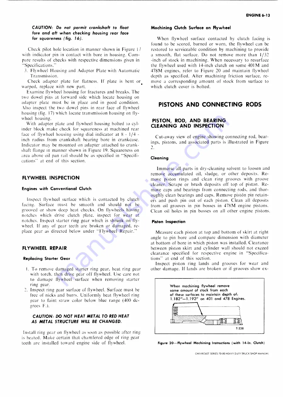
the flywheel used with 14-inch clutch on some 401 M and
478M engines, refer to Figure 20 and maintain flywheel
depth as specified. After machining friction surface, re
move a corresponding am ount of stock from surface to
which clutch cover is bolted.
PISTO N S A N D C O N N E C T IN G RODS
PISTO N , ROD, A N D B E A R IN G
C L E A N IN G A N D IN S P E C T IO N
Cut-away view of engine showing connecting rod, bear
ings, pistons, and associated parts is illustrated in Figure
2,
Cleaning
Immerse all parts in dry-cleaning solvent to loosen and
remove accumulated oil, sludge, or other deposits. R e
move piston rings and clean ring grooves with groove
cleaner. Scrape or brush deposits off top of piston. R e
move caps and bearings from connecting rods, and thor
oughly clean bearings and caps. Remove piston pin retain
ers and push pin out of each piston. Clean all deposits
from oil grooves in pin bosses in 478M engine pistons.
Clean oil holes in pin bosses on all other engine pistons.
Piston Inspection
Measure each piston at top and bottom of skirt at right
angle to pin bore and compare dimension with diameter
at bottom of bore in which piston was installed. Clearance
between piston skirt and cylinder wall should not exceed
clearance specified for respective engine in “ Specifica
tions" at end of this section.
Inspect piston ring lands and grooves for wear and
other damage. If lands are broken or if grooves show ex-
W h e n m a c h in in g fly w h e e l re m o v e
s a m e a m o u n t o f sto c k fr o m e a c h
o f th e se s u r fa c e s to m a in ta in d e p th of:
1.1 8 2 " — 1 . 1 9 2 " on 4 0 1 a n d 4 7 8 E n g in e s.
T-338
Figure 2 0 — Flyw h eel M a c h in in g Instructions (w ith 14-In. Clutch)
CHEVROLET SERIES 70-80 HEAVY DUTY TRUCK SH O P M A N U A L
Summary of Contents for 70 1969 Series
Page 1: ...CHEVROLET HEAVY DUTY TRUCK SHOP MANUAL...
Page 3: ......
Page 11: ...LUBRICATION 0 4 CHEVROLET SERIES 70 80 HEAVY DUTY TRUCK SHOP MANUAL...
Page 27: ......
Page 119: ......
Page 361: ......
Page 371: ......
Page 427: ......
Page 443: ......
Page 451: ......
Page 493: ......
Page 499: ......
Page 549: ......
Page 555: ......
Page 609: ......
Page 715: ...am...
Page 745: ......
Page 910: ......
Page 913: ......


