REAR AXLE 4-12
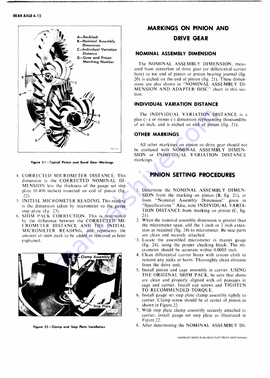
Figure 2 1 — T yp ical Pinion a n d Bevel G e a r M a r k in g s
4. C O R R E C T E D M IC R O M E T E R D IS T A N C E . This
dimension is the C O R R E C T E D N O M IN A L D I
M E N S IO N less the thickness of the gauge set step
plate (0.400 inches) m ounted on end of pinion (fig.
2 2
).
5. IN IT IA L M IC R O M E T E R R E A D IN G . This reading
is the dim ension taken by m icrom eter to the gauge
step plate (fig. 23).
6. S H IM PA C K C O R R E C T IO N . This is determ ined
by the difference between the C O R R E C T E D M I
C R O M E T E R D IS T A N C E A N D T H E IN IT IA L
M IC R O M E T E R R E A D IN G , and represents the
am ount of shim pack to be added or removed as later
explained.
Figure 2 7 — C lam p an d Step Plate Installation
M A R K IN G S O N P IN IO N A N D
DRIVE G E A R
NOMINAL ASSEMBLY DIMENSION
The N O M IN A L A S S E M B L Y D IM E N S IO N , m eas
ured from centerline of drive gear (or differential carrier
bore) to toe end of pinion or pinion bearing journal (fig.
20) is etched on the end of pinion (fig. 21). These dim en
sions are also shown in “ N O M IN A L A S S E M B L Y D I
M E N S IO N A N D A D A P T E R D IS C ” chart in this sec
tion.
INDIVIDUAL VARIATION DISTANCE
The IN D IV ID U A L V A R IA T IO N D IS T A N C E is a
plus (+ ) or minus (-) dim ension representing thousandths
of an inch, and is etched on end of pinion (fig. 21).
OTHER MARKINGS
All other m arkings on pinion or drive gear should not
be confused with N O M IN A L A S S E M B L Y D I M E N
S IO N or IN D IV ID U A L V A R IA T IO N D IS T A N C E
markings.
P IN IO N SETTING PRO CEDURES
1. D eterm ine the N O M IN A L A S S E M B L Y D I M E N
S IO N from the m arking on pinion (B, fig. 21), or
from “ N o m inal Assembly D im ension” given in
“ Specifications.” Also, note IN D IV ID U A L V A R IA
T IO N D IS T A N C E from m arking on pinion (C, fig.
2 1
).
2. W hen the nom inal assembly dim ension is greater than
the m icrom eter span, add the 1 inch or 2 inch exten
sion as required (fig. 24) to m icrom eter. Be sure parts
are clean and securely attached.
'3. Locate the assembled m icrom eter in m aster gauge
(fig. 24), using the proper checking block. The m i
crom eter should be accurate within 0.0005 inch.
4. Clean differential carrier bores with crocus cloth to
remove any nicks or burrs. T horoughly clean abrasive
from the drive unit.
5. Install pinion and cage assem bly in carrier. U S IN G
T H E O R IG IN A L S H IM P A C K , be sure that shims
are clean and properly aligned with oil passages in
cage and carrier. Install cap screws and T IG H T E N
T O R E C O M M E N D E D T O R Q U E .
6. Install gauge set step plate clam p assem bly tightly to
carrier. C lam p screw should be at center of pinion as
shown in Figure 22.
7. W ith step plate clam p assem bly securely attached to
carrier, install gauge set step plate as illustrated in
Figure 22.
8. After determ ining the N O M IN A L A S S E M B L Y DI-
CHEVROLET SERIES 70-80 H EAVY DUTY TRUCK SH O P M A N U A L
Summary of Contents for 70 1969 Series
Page 1: ...CHEVROLET HEAVY DUTY TRUCK SHOP MANUAL...
Page 3: ......
Page 11: ...LUBRICATION 0 4 CHEVROLET SERIES 70 80 HEAVY DUTY TRUCK SHOP MANUAL...
Page 27: ......
Page 119: ......
Page 361: ......
Page 371: ......
Page 427: ......
Page 443: ......
Page 451: ......
Page 493: ......
Page 499: ......
Page 549: ......
Page 555: ......
Page 609: ......
Page 715: ...am...
Page 745: ......
Page 910: ......
Page 913: ......


