E N G IN E 6-30
C AU TIO N : The
"quick,
firm
push"
replaces the
m ethod of gently tapping a piston into the
block. Tapping the piston into place could result
in the edges o f ring slipping from beneath the
com pressor a n d preven ting entrance of the ring
into the bore. If entrance is accom plished under
this condition, the ring segm ents could be bent
an d cause im proper ring function.
e. Using handle on guide set (fig. 5), pull connecting
rod firmly into contact with crankpin, then install
cap and lower bearing half on respective connect
ing rod. Lubricate threads in nuts and on bolts
with S.A.E. 10 engine oil, then install nuts on
connecting rod bolts. Side of nut having larger
chamfer must be away from connecting rod cap.
Tighten bolt nuts to 55 to 65 foot-pounds with
torque wrench. Try moving connecting rod end
wise on crankpin. Rod should move freely with
nuts tightened firmly.
C AU TIO N : Do not file or shim bearing caps to
obtain a fit. Select an insert w hich w ill provide
correct vertical clearance of
0.0010
to 0 .0 0 3 0
inch.
OIL PUMP INSTALLATION
Refer to Figure 49.
1. Place new' oil pump to cylinder block gasket at
mounting flange and insert pu m p drive shaft in socket
in pum p shaft, or if engine is inverted, set pum p drive
shaft in place at distributor. Start pum p mounting
bolts, but do not tighten.
2. Install governor line between fitting in side of
crankcase and fitting on governor spinner housing at
oil pump. Before tightening governor line nuts, tighten
oil pum p mounting bolts.
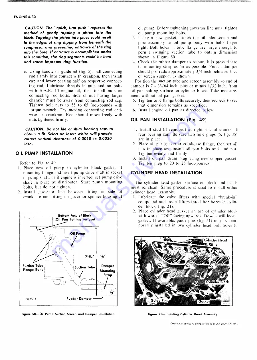
3. Using a new gasket, attach the oil inlet screen and
pipe assembly to oil pum p body with bolts finger
tight. Bolt holes in tube flange are large enough to
pern it swinging suction tube to obtain dimension
shown in Figure 50
4. Check the rubber damper to be sure it is pressed into
its mounting strap as far as possible. End of damper
should protrude approximately 3 /4 inch below surface
of screen support as shown.
Position the suction tube and screen assembly so end of
dam per is 7 - 33/64 inch, plus or minus 1/32 inch, from
oil pan bolting surface on cylinder block. T ake measure
ment without oil pan gasket.
5. Tighten tube flange bolts securely, then recheck to see
that dimension remains as specified.
6. Install engine oil pan as directed below:
OIL PAN INSTALLATION (Fig. 49)
1. Install stud (if removed) at right side of crankshaft
rear bearing cap. Be sure two hole plugs (5, fig. 35)
are in place.
2. Place oil pan gasket at crankcase flange, then set oil
pan in place and install oil pan bolts and stud nut.
Tighten evenly and firmly.
3. Install oil pan drain plug using new copper gasket.
Tighten plug to 20 to 25 foot-pounds.
CYLINDER HEAD INSTALLATION
The cylinder head gasket surface on block and heads
must be clean. S am e procedure is used to install either
cylinder head assembly.
1. Lubricate the valve lifters with special “ break-in”
compound and insert lifters into lifter bores in cylin
der block (fig. 21).
2. Place cylinder head gasket on top of cylinder bicek
with word “ T O P ” facing upwards. Dowels will locate
gasket. If available, guide pins (fig. 51) may be tem
porarily installed in two cylinder head bolt holes to
Figure 5 1 — In sta llin g C y lin d e r H e a d A sse m b ly
CHEVROLET SERIES 70-80 HEAVV DUTY TRUCK SH O P M A N U A L
Summary of Contents for 70 1969 Series
Page 1: ...CHEVROLET HEAVY DUTY TRUCK SHOP MANUAL...
Page 3: ......
Page 11: ...LUBRICATION 0 4 CHEVROLET SERIES 70 80 HEAVY DUTY TRUCK SHOP MANUAL...
Page 27: ......
Page 119: ......
Page 361: ......
Page 371: ......
Page 427: ......
Page 443: ......
Page 451: ......
Page 493: ......
Page 499: ......
Page 549: ......
Page 555: ......
Page 609: ......
Page 715: ...am...
Page 745: ......
Page 910: ......
Page 913: ......


