POWER BRAKE 5-27
9. Discard all grom m ets.
CLEANING AND INSPECTION
W ash all metal parts in a good cleaning solvent. Dry
thoroughly. W ipe reusable rubber parts clean. Inspect all
parts for excessive wear or deterioration. Inspect plunger
and piston bores for nicks and burrs. Check springs for
cracks, distortion and corrosion. Inspect the inlet and ex
haust valve and all grom m ets for wear or deterioration.
Replace all parts not considered serviceable, especially
rubber parts.
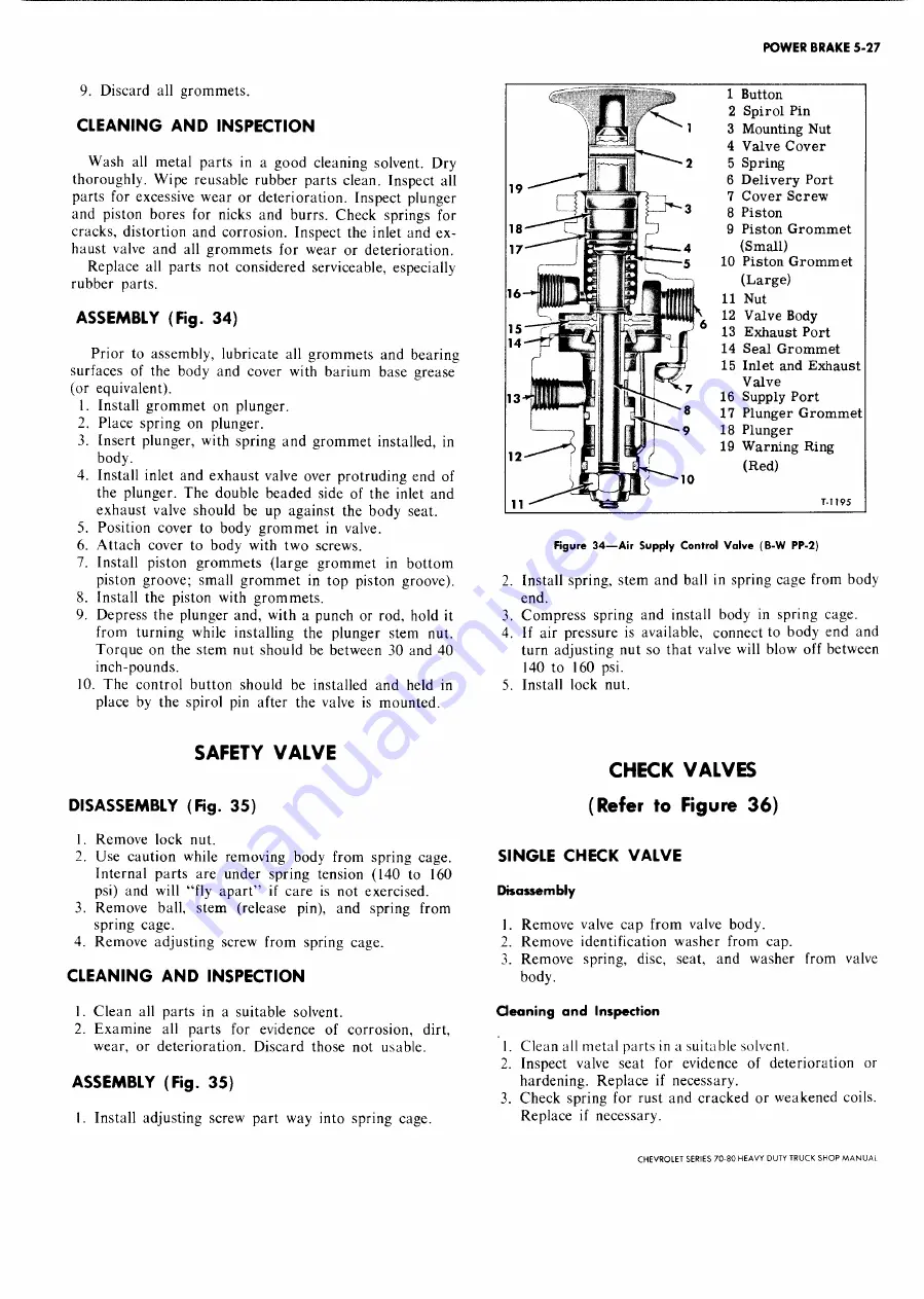
ASSEMBLY (Fig. 34)
Prior to assembly, lubricate all grom m ets and bearing
surfaces of the body and cover with barium base grease
(or equivalent).
1. Install grom m et on plunger.
2. Place spring on plunger.
3. Insert plunger, with spring and grom m et installed, in
body.
4. Install inlet and exhaust valve over protruding end of
the plunger. The double beaded side of the inlet and
exhaust valve should be up against the body seat.
5. Position cover to body g ro m m et in valve.
6. A ttach cover to body with tw o screws.
7. Install piston grom m ets (large grom m et in bottom
piston groove; small g ro m m et in top piston groove).
8. Install the piston with grom m ets.
9. Depress the plunger and, with a punch or rod, hold it
from turning while installing the plunger stem nut.
Torque on the stem nut should be between 30 and 40
inch-pounds.
10. T he control button should be installed and held in
place by the spirol pin after the valve is m ounted.
n <
l
2
Button
Spirol Pin
t i ,
3 Mounting Nut
4 Valve Cover
5 Spring
19 -—
6 Delivery Port
7 Cover Screw
... M
^ 3
8 Piston
1 7 ^ --
9 Piston Grommet
(Small)
iff" I D T —
~5
10 Piston Grommet
MMM
h
H f IgJ
—
(Large)
16~*|lll
I P illfflU
11 Nut
X.
12 Valve Body
1 5 ""T ~ S p S p l g = a | ^ g ' O
13 Exhaust Port
M
| llj^I
14 Seal Grommet
15 Inlet and Exhaust
Valve
13 jlll
11
I jW
16 Supply Port
1 T ,
8
17 Plunger Grommet
*--- } 1
! ( | j
^ 9
18 Plunger
i 2^
i
f Jijx
19 Warning Ring
(Red)
10
T - l l 95
Figu re 3 4 — A ir S u p p ly C o n tro l V a lv e (B - W PP-2)
2. Install spring, stem and ball in spring cage from body
end.
3. C om press spring and install body in spring cage.
4. If air pressure is available, connect to body end and
turn adjusting nut so that valve will blow off between
140 to 160 psi.
5. Install lock nut.
SAFETY VALVE
DISASSEMBLY (Fig. 35)
1. Remove lock nut.
2. Use caution while removing body from spring cage.
Internal parts are under spring tension (140 to 160
psi) and will “ fly ap art” if care is not exercised.
3. Remove ball, stem (release pin), and spring from
spring cage.
4. Rem ove adjusting screw from spring cage.
CLEANING AND INSPECTION
1. C lean all parts in a suitable solvent.
2. E xam ine all parts for evidence of corrosion, dirt,
wear, or deterioration. D iscard those not usable.
ASSEMBLY (Fig. 35)
I. Install adjusting screw part way into spring cage.
CHECK VALVES
(Refer to Figure 36)
SINGLE CHECK VALVE
Disassembly
1. Remove valve cap from valve body.
2. Rem ove identification w asher from cap.
3. Rem ove spring, disc, seat, and washer from valve
body.
Oeaning and Inspection
1. Clean all m etal parts in a suitable solvent.
2. Inspect valve seat for evidence of deterioration or
hardening. Replace if necessary.
3. C heck spring for rust and cracked or weakened coils.
Replace if necessary.
CHEVROLET SERIES 70-80 HEAVY DUTY TRUCK SHOP M A N U A L
Summary of Contents for 70 1969 Series
Page 1: ...CHEVROLET HEAVY DUTY TRUCK SHOP MANUAL...
Page 3: ......
Page 11: ...LUBRICATION 0 4 CHEVROLET SERIES 70 80 HEAVY DUTY TRUCK SHOP MANUAL...
Page 27: ......
Page 119: ......
Page 361: ......
Page 371: ......
Page 427: ......
Page 443: ......
Page 451: ......
Page 493: ......
Page 499: ......
Page 549: ......
Page 555: ......
Page 609: ......
Page 715: ...am...
Page 745: ......
Page 910: ......
Page 913: ......


