BRAKES 5B-31
♦ i
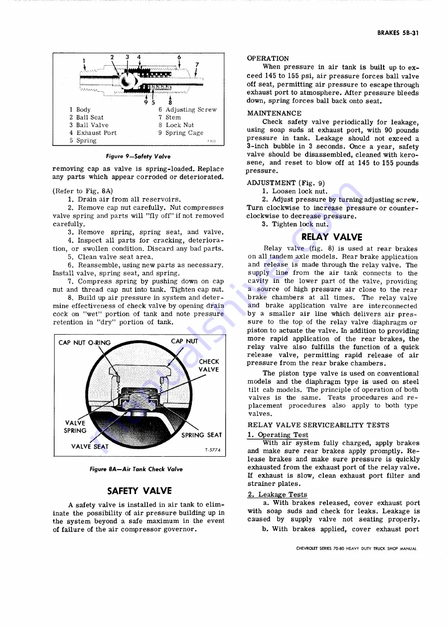
Body
Ball Seat
Ball Valve
Exhaust Port
Spring
i
9 5
8
6 Adjusting Screw
7 Stem
8 Lock Nut
9 Spring Cage
Figure 9— Safely Valve
removing cap as valve is spring-loaded. Replace
any parts which appear corroded or deteriorated.
(Refer to Fig. 8A)
1. Drain air from all reservoirs.
2. Remove cap nut carefully. Nut compresses
valve spring and parts will "fly off" if not removed
carefully.
3. Remove spring, spring seat, and valve.
4. Inspect all parts for cracking, deteriora
tion, or swollen condition. Discard any bad parts.
5. Clean valve seat area.
6 . Reassemble, using new parts as necessary.
Install valve, spring seat, and spring.
7. Compress spring by pushing down on cap
nut and thread cap nut into tank. Tighten cap nut.
8. Build up air pressure in system and deter
mine effectiveness of check valve by opening drain
cock on "wet" portion of tank and note pressure
retention in "dry" portion of tank.
CAP NUT O -R IN G
CAP NUT
CHECK
V A L V E
VA LVE
S P R IN G
VA LVE SEAT
S P R IN G SEAT
Figure 8 A — Air Tank Check Valve
SAFETY VALVE
A safety valve is installed in air tank to elim
inate the possibility of air pressure building up in
the system beyond a safe maximum in the event
of failure of the air compressor governor.
O P E R A T IO N
When pressure in air tank is built up to ex
ceed 145 to 155 psi, air pressure forces ball valve
off seat, permitting air pressure to escape through
exhaust port to atmosphere. After pressure bleeds
down, spring forces ball back onto seat.
M A IN T E N A N C E
Check safety valve periodically for leakage,
using soap suds at exhaust port, with 90 pounds
pressure in tank. Leakage should not exceed a
3-inch bubble in 3 seconds. Once a year, safety
valve should be disassembled, cleaned with kero
sene, and reset to blow off at 145 to 155 pounds
pressure.
A D J U S T M E N T (Fig. 9)
1. Loosen lock nut.
2. Adjust pressure by turning adjusting screw.
Turn clockwise to increase pressure or counter
clockwise to decrease pressure.
3. Tighten lock nut.
RELAY VALVE
Relay valve (fig. 8) is used at rear brakes
on all tandem axle models. Rear brake application
and release is made through the relay valve. The
supply line from the air tank connects to the
cavity in the lower part of the valve, providing
a source of high pressure air close to the rear
brake chambers at all times. The relay valve
and brake application valve are interconnected
by a smaller air line which delivers air pres
sure to the top of the relay valve diaphragm or
piston to actuate the valve. In addition to providing
more rapid application of the rear brakes, the
relay valve also fulfills the function of a quick
release valve, permitting rapid release of air
pressure from the rear brake chambers.
The piston type valve is used on conventional
models and the diaphragm type is used on steel
tilt cab models. The principle of operation of both
valves is the same. Tests procedures and re
placement procedures also apply to both type
valves.
R E L A Y V A L V E SER V IC E A B IL IT Y T E S T S
1. Operating Test
With air system fully charged, apply brakes
and make sure rear brakes apply promptly. R e
lease brakes and make sure pressure is quickly
exhausted from the exhaust port of the relay valve.
If exhaust is slow, clean exhaust port filter and
strainer plates.
2. Leakage Tests
a. With brakes released, cover exhaust port
with soap suds and check for leaks. Leakage is
caused by supply valve not seating properly.
b. With brakes applied, cover exhaust port
CHEVROLET SERIES 70-80 H EAVY DUTY TRUCK SH O P M A N U A L
Summary of Contents for 70 1969 Series
Page 1: ...CHEVROLET HEAVY DUTY TRUCK SHOP MANUAL...
Page 3: ......
Page 11: ...LUBRICATION 0 4 CHEVROLET SERIES 70 80 HEAVY DUTY TRUCK SHOP MANUAL...
Page 27: ......
Page 119: ......
Page 361: ......
Page 371: ......
Page 427: ......
Page 443: ......
Page 451: ......
Page 493: ......
Page 499: ......
Page 549: ......
Page 555: ......
Page 609: ......
Page 715: ...am...
Page 745: ......
Page 910: ......
Page 913: ......


