4
-
9
4
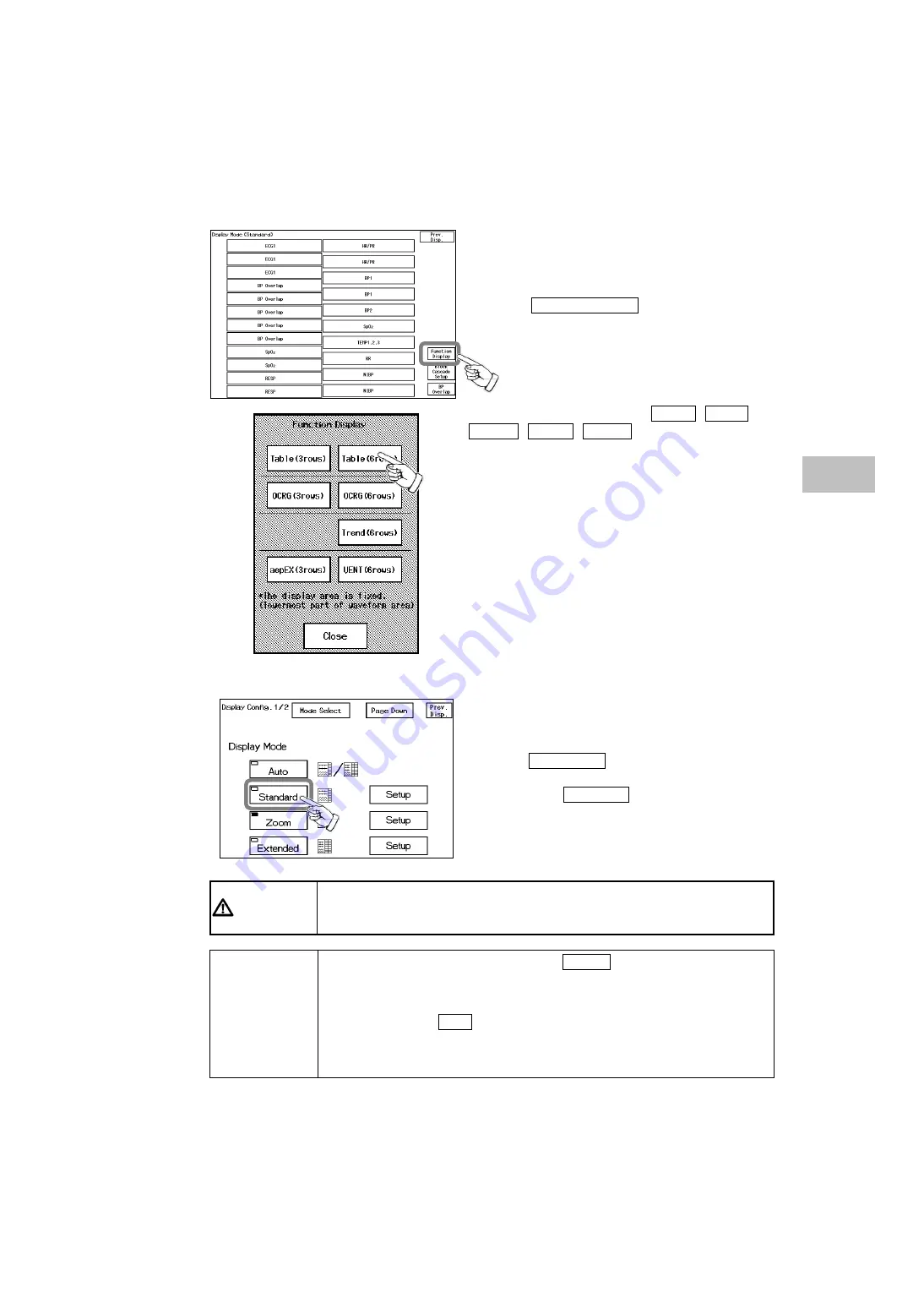
Select the function display.
Press the Function Display key to display the
function display selection window.
Select the function display from Trend , Table ,
OCRG , VENT , aepEX .
3 rows / 6 rows indicates the size to display the table and
OCRG.
<
Function Display Tool
>
5
Select “Standard” for the display mode.
Press the Prev. Disp. key to return to the display
configuration menu.
Then, press the Standard key for the display mode.
C A U T I O N
If performing telemetry or wired network transmission, configure the display so
that the numeric data corresponding to the waveform is displayed.
If not, the displayed waveform or numeric data may not be transmitted.
N O T E
z
After configuring the display, press the Home key to verify the
programmed display configuration.
z
To maintain the configured display even after the power is turned OFF or
after a discharge procedure, save the configuration to one of the display
modes, or select ON for “Backup at Discharge” on the ”Discharge Setup”
under the Initial Settings.
For display mode setup procedure, refer to “9. Initial Settings –Display Mode
Setup–”.
4
Displa
y Co
nfiguratio
n Setu
p
Summary of Contents for DynaScope 7000 Series
Page 38: ...xxxvi Blank Page ...
Page 126: ...4 78 Blank Page ...
Page 148: ...5 22 Blank Page ...
Page 259: ...7 15 The Description of the Display Scale Real Time Scale Scale 7 Table Trend ...
Page 322: ...7 78 Blank Page ...
Page 428: ...10 32 Blank Page ...
Page 466: ...11 38 Blank Page ...
Page 474: ...12 8 Blank Page ...


