Concepts and features
R&S
®
ZNA
183
User Manual 1178.6462.02 ─ 20
4.5.5.3
Characterization of calibration units
Each calibration unit is delivered with factory characterization data which ensure an
accurate calibration for all standard applications. For specific modifications of the test
setup, e.g. the connection of additional adapters to a calibration unit, a modified set of
characterization data (suitable for the cal unit with adapters) may be desirable. The
R&S
ZNA provides a characterization wizard which you can use to generate your own
characterization data sets for (modified) R&S cal units. The characterization data can
be stored in the cal unit and used for automatic calibration whenever needed.
A cal unit characterization can be performed in a frequency sweep. The network ana-
lyzer must be properly calibrated, with the reference plane at the input ports of the
(modified) cal unit to be characterized.
The procedure involves the following steps:
1. Perform a calibration of your network analyzer, using the test setup and the calibra-
tion type you wish to perform with your calibration unit.
2. Connect the calibration unit to the network analyzer.
3. Access the "Characterize Cal Unit" dialog (Channel – [Cal] > "Cal Devices" >
"Characterize Cal Unit...") and select "Start Characterization...".
4. Step through the "Characterization" wizard, following the instructions in the dialogs.
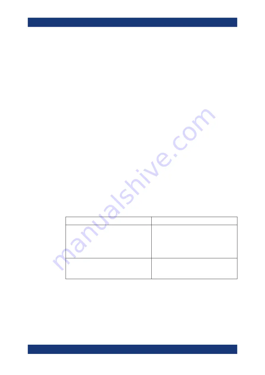
Dependency between calibration types and characterization data
A cal unit characterization provides full one-port (OSM) data at the selected ports plus
two-port (Through) data between any pair of selected ports. The measurement of
Through data is optional, however, it is required for some calibration types. The follow-
ing table gives an overview.
Calibration type
Characterization data required
Refl Norm Open
Refl Norm Short
Refl OSM
UOSM
TOSM
OSM CalPort 1, OSM CalPort2 ... (all calibrated
ports)
Trans Norm Both
Trans Norm Forward
One Path Two Ports
OSM CalPort 1, OSM CalPort2 ... (all calibrated
ports), Through (between all pairs of ports)
4.5.5.4
Inline calibration
Any disturbance of the measurement setup after the calibration process inevitably pro-
duces errors. If a massive system error correction is required, e.g. if long RF cables
with high damping are used, those disturbances can lead to inaccurate and unreprodu-
cible measurement results. Especially in remote scenarios, such as measurements in a
Calibration


