3
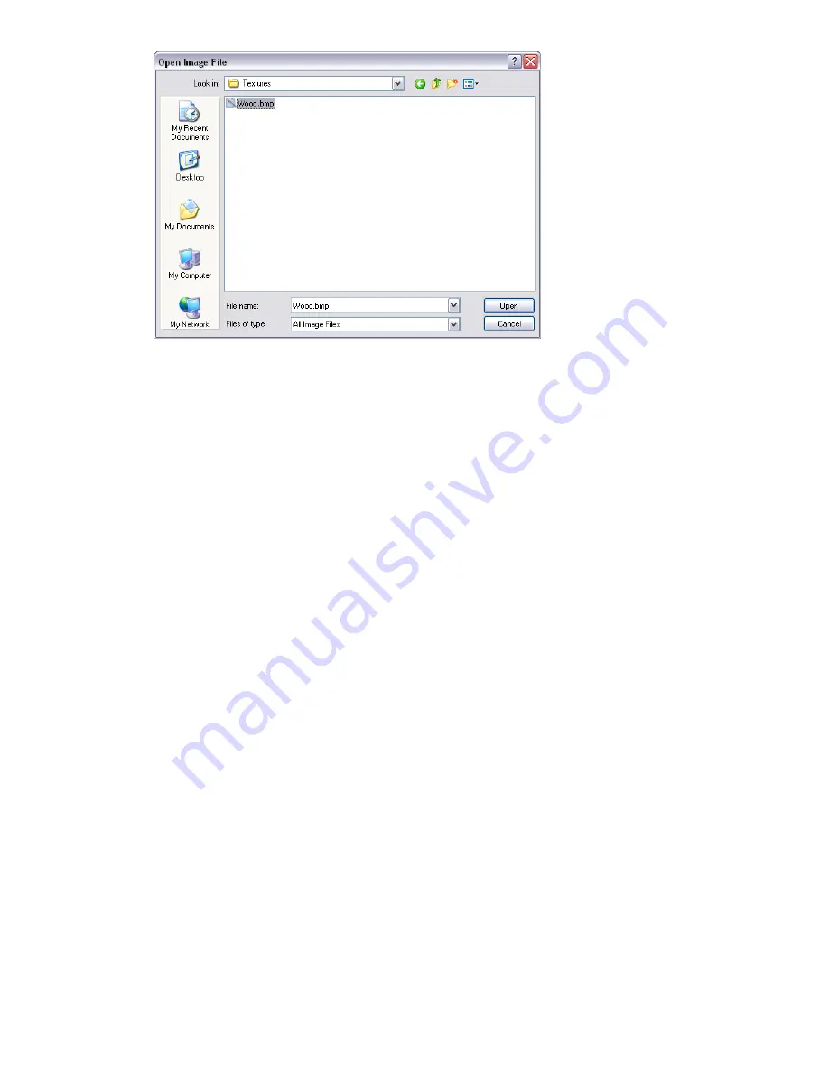
Browse to the location of and select your image file, then click Open.
4
You may then need to adjust some of the texture parameters of the new material, for example its scale,
rotation, offset or reflection (if it's back to front). These may all be edited in the Texture tab. See “
” on page 306 for more information.
Advanced Materials
Internally a material is defined by four shaders from different classes - Color, Transparency, Reflectance and
Displacement. Each class of shader controls a different aspect of a material's behavior. There are many types of
shader in each class, each type being defined by its own set of parameters.
■
A
color
shader is used to define the color of a surface at any point in space. It may be as simple as a plain
color which specifies all parts of the surface to have a uniform color, or it may define complex surface patterns
such as marble or wood. Every material must have a color shader.
■
A
transparency
shader is used to define how transparent or opaque a surface is, and thus how much light is
able to pass through it. Transparency shaders range from a simple uniform transparency to more complex
regular or irregular eroded patterns that would be more difficult to represent using modelling techniques. A
material without a transparency shader is completely opaque.
■
The behavior of a surface in the presence light is represented by a
reflectance
shader which defines how
much light is reflected by the surface towards the viewer. Shaders of this class may be thought of as defining
a surface's “finish”, and are used to model properties such as matte, metal and plastic.
■
Small surface perturbations can be supported by means of displacement shaders. Typically, a displacement
shader will give an otherwise smooth surface an irregular or indented appearance. Displacement shaders are
used to represent features that would be difficult, impossible, or inefficient if conventional modelling
techniques were used. For example, rough metal castings and the regular indentations produced by pressed
sheet metal can be simulated.
Normally, the Material Editor displays a selection of the most important parameters from all shaders within the
material tab. If the user profile is set to Developer in the Options Editor (see “
” on page 436), then
all four shaders can be edited and changed individually.
Some shaders are described as “wrapped”. These define a flat, two dimensional material, like wall paper. Wrapped
materials need a texture space shader to define how they should be applied to (wrapped around) a three
dimensional object. Materials that include a wrapped shader can also include a texture space shader. A special
type of texture space shader, called a layout shader, can be used to transform (rotate, stretch, offset) the two
dimensional material before it is applied to the three dimensional object. Transforms are based around an origin
point, which by default, is the top left hand corner of the image (refer to the diagram below, where the image
is inscribed in the red square, which is then repeated. The default origin is
Point 1
). Selecting the Offset Center
Advanced Materials | 309
Summary of Contents for 507B1-90A211-1301 - NavisWorks Manage 2010
Page 1: ...Autodesk Navisworks Manage 2010 User Guide March 2009 ...
Page 12: ...xii Contents ...
Page 14: ...2 Part 1 Welcome to Autodesk Navisworks Manage 2010 ...
Page 64: ...52 Chapter 3 Installation ...
Page 97: ...Get a Whole Project View 85 ...
Page 98: ...86 Part 2 Get a Whole Project View ...
Page 136: ...124 Chapter 5 Work with Files ...
Page 178: ...To toggle ViewCube Click View Head Up Display ViewCube 166 Chapter 6 Explore Your Model ...
Page 262: ...250 Chapter 9 Use Viewpoints and Sectioning Modes ...
Page 270: ...258 Chapter 11 Work Within a Team ...
Page 282: ...270 Chapter 12 Share Data ...
Page 346: ...334 Chapter 14 Create Photorealistic Visualizations ...
Page 460: ...448 Chapter 17 Autodesk Navisworks Reference ...
Page 466: ...454 Glossary ...


