


3–6 • Preliminary Cabling and Check
Synergy 100 Installation Guide (v16.10-S100)
Resetting the System
If required, the Synergy 100 SD switcher can be reset manually from the frame. A
Full Reset
affects
hardware and software simultaneously.
Full Reset
This function performs both a hardware and a software reset simultaneously. Switcher memory
registers, personality registers, and installation registers are not affected by the reset, but all other
switcher parameters (for example, the current state of the panel) are reset.
BLACK
will be selected on
all buses.
•
To reset the frame and all system hardware and software, press the blue
RESET
button
on the front edge of the
Frame CPU Board
.
Refer to the section “
” on page 2–20 for more information on the
frame
RESET
switch.
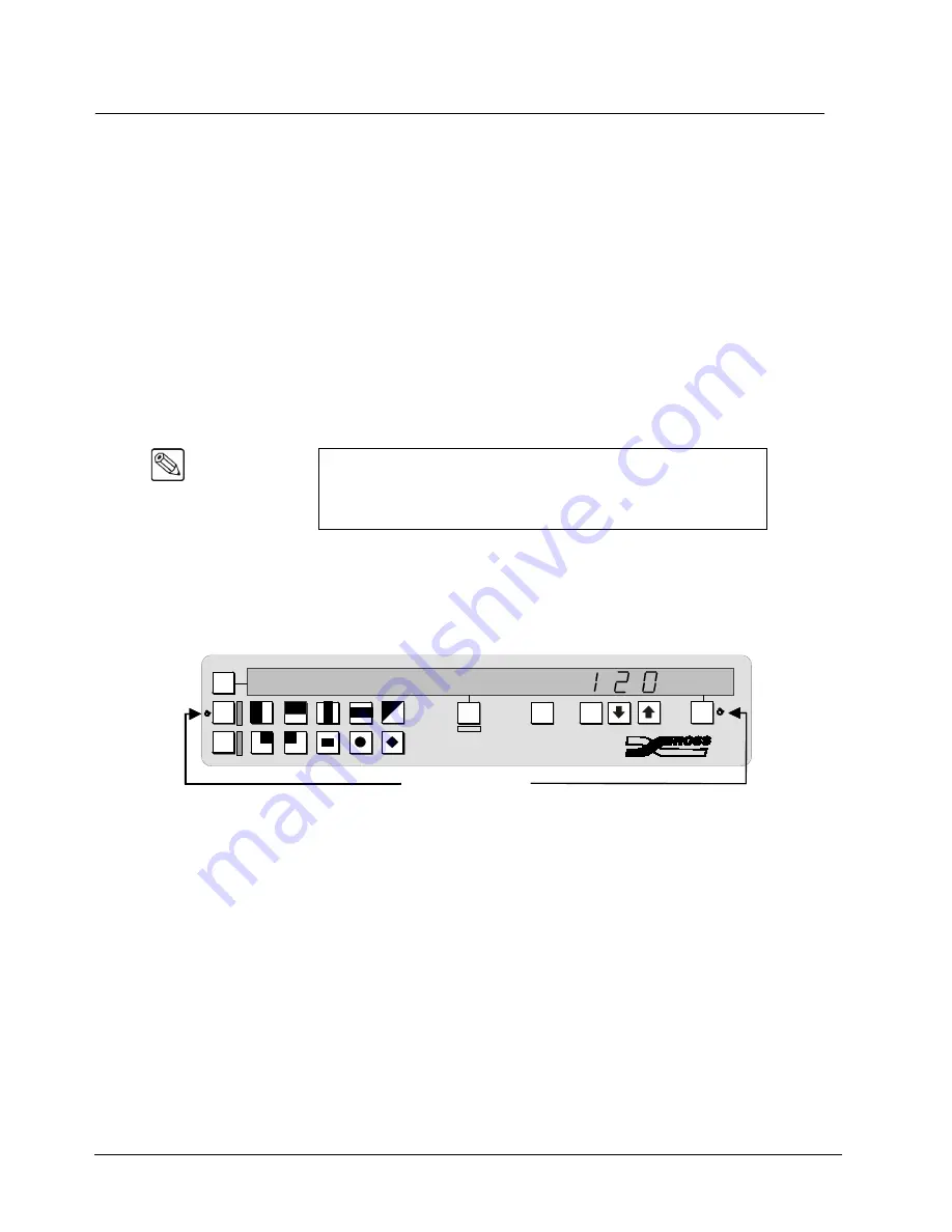
Software Reset
The software reset function is performed in the
Effects Control
and
System Control
groups. Use the
following figure for reference:
Software Reset Function
•
To perform a full software reset, simultaneously press
CNTR/EFF D
in the
Effects
Control
group and
SEL
in the
System Control
group.
BLACK
will be selected on all
buses.
Note
It is not recommended to reset the frame by turning the power off and
then on. However if this is done, the frame software will be reloaded,
but the panel settings will come back to the point they were at, before
the loss of power.
E
FFECTS
C
ONTROL
S
YSTEM
C
ONTROL
SEL
CNTR
REV
MENU
SEL
EDIT
BACK
100
10
1
SEL
L
E
A
R
N
0
1
2
3
4
5
6
7
8
9
MODE
AUTO
M
ATTES
MODE
BKGD
MODE
WIPE
Press simultaneously
to reset control panel
E
F
F
D
D VE
Содержание Synergy 100
Страница 1: ...Ross Video Limited Installation Guide Software Issue 16 10 S100...
Страница 10: ......
Страница 16: ...vi Contents Synergy 100 Installation Guide v16 10 S100...
Страница 66: ...2 32 Installation Synergy 100 Installation Guide v16 10 S100...
Страница 88: ...5 6 Using the Menu System Synergy 100 Installation Guide v16 10 S100...
Страница 100: ...6 12 BNC Configuration and Check Synergy 100 Installation Guide v16 10 S100...
Страница 134: ...7 34 Communication Setup Synergy 100 Installation Guide v16 10 S100...
Страница 170: ...8 36 Additional Installation Setups Synergy 100 Installation Guide v16 10 S100...
Страница 186: ...9 16 Completing Setup Synergy 100 Installation Guide v16 10 S100...
Страница 208: ...10 22 Appendix A Specifications Synergy 100 Installation Guide v16 10 S100...
Страница 216: ...11 8 Appendix B Hardware Options Synergy 100 Installation Guide v16 10 S100...
Страница 234: ...GL 4 Glossary of Terms Synergy 100 Installation Guide v16 10 S100...
Страница 246: ...IX 12 Index Synergy 100 Installation Guide v16 10 S100...