


Synergy 100 Installation Guide (v16.10-S100)
Additional Installation Setups • 8–11
crosspoints are being selected (remotely, by another user), but you
cannot
change crosspoints on the current panel.
•
Repeat for each of the 8 Aux Buses.
Dedicated Remote Aux Panel
5. To select the Aux Bus output that you wish to control and assign the “rights” for a
dedicated
panel, perform the following steps at
each
dedicated panel connected to the
switcher:
•
Ensure that the panel is in “programming” mode (with the on-air LED flashing).
•
Press the crosspoint button (
3
-
8
) that corresponds to the single Aux Bus that you
want to control at the current panel. By selecting a button, you are telling the
switcher that the current dedicated panel now controls the associated Aux Bus
output.
•
To assign the “rights” to the current panel, use the same crosspoint button as in step
b) above. Note that
each
press of the button toggles between two states:
~
On
— When the button is lit steadily, the selected Aux Bus output is in “full
access” or “regular” mode. The Aux Bus can be selected and sources can be
changed from both the remote Aux panel and the
local
control panel.
~
Flashing
— When the button’s light is flashing, the associated Aux Bus is in
“follow”
or “view only” mode. You can follow what crosspoints are being
selected (remotely, by another user), but you cannot change crosspoints on the
current dedicated panel.
6. Press
MENU
to display the
Installation Change Screen
.
7. Accept or cancel these changes as follows:
•
Press
0. Confirm
to accept the changes.
•
Press
1. Cancel
to exit the menus safely, without making any changes. The system
returns to the previously stored settings.
This completes the procedure to set up your Remote Aux Panels. All Remote Aux Panels return to
their normal operating mode. In addition, each panel’s new “rights” are stored in the remote panel’s
non-volatile memory.
The next procedure is to set up the desired group and offset for each Remote Aux Panel.
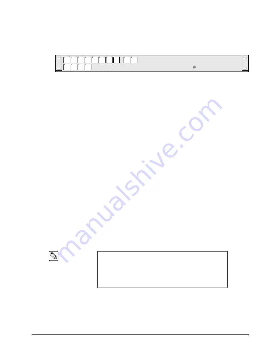
Note
Special modes such as the
PRG/Key SHIFT
mode are not available
on remote panels.
For reference only,
note the state of the
SHIFT
button (#10) — but
do
not
change its state. If the button is lit, shifted crosspoints are allowed
on the panel. If the button is off, shifted crosspoints cannot be selected.
This mode is set
automatically
to match that of the main Control Panel.
BLACK
2
3
4
5
6
7
8
9
MLE
PV
CLEAN
FEED
PGM
1
SHIFT
10
DVE
SEND
Содержание Synergy 100
Страница 1: ...Ross Video Limited Installation Guide Software Issue 16 10 S100...
Страница 10: ......
Страница 16: ...vi Contents Synergy 100 Installation Guide v16 10 S100...
Страница 66: ...2 32 Installation Synergy 100 Installation Guide v16 10 S100...
Страница 88: ...5 6 Using the Menu System Synergy 100 Installation Guide v16 10 S100...
Страница 100: ...6 12 BNC Configuration and Check Synergy 100 Installation Guide v16 10 S100...
Страница 134: ...7 34 Communication Setup Synergy 100 Installation Guide v16 10 S100...
Страница 170: ...8 36 Additional Installation Setups Synergy 100 Installation Guide v16 10 S100...
Страница 186: ...9 16 Completing Setup Synergy 100 Installation Guide v16 10 S100...
Страница 208: ...10 22 Appendix A Specifications Synergy 100 Installation Guide v16 10 S100...
Страница 216: ...11 8 Appendix B Hardware Options Synergy 100 Installation Guide v16 10 S100...
Страница 234: ...GL 4 Glossary of Terms Synergy 100 Installation Guide v16 10 S100...
Страница 246: ...IX 12 Index Synergy 100 Installation Guide v16 10 S100...