


16 - 17
Chapter 16 Troubleshooting
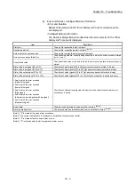
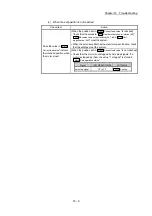
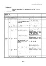
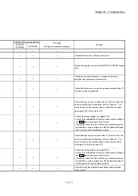
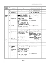
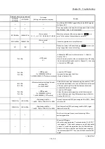
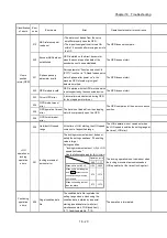
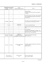
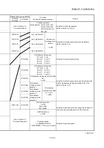
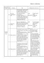
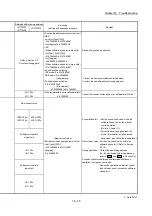
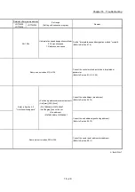
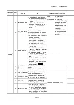
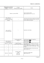
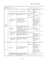
Related buffer memory address
Set range
(Setting with sequence program)
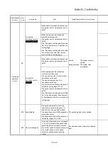
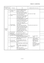
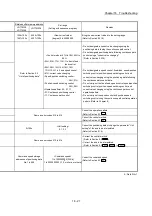
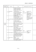
Remedy
LD77MS2
LD77MS4
LD77MS16
— —
—
—
—
—
—
Check that there is no influence from noise.
— —
—
Review the program which turns ON/OFF PLC READY signal
[Y0].
— —
—
Check the servo amplifier power, wiring with the servo
amplifier, and connection of connectors.
— —
—
Check that there is no error on the personal computer side I/F
to which a cable is connected.
— —
—
After making an axis error reset (refer to [3] in Section 16.4),
perform manual control operation (refer to Chapter 11) to
move the axis to the other position in order that the upper
limit signal (FLS) will not turn OFF.
— —
—
• Check the wiring of upper limit signal FLS.
• Check if the specification of the limit switch and the setting of
the "
Pr.22
Input signal logic selection
" match.
• If hardware stroke limit (limit switch) is unnecessary system
for installation, wire to always turn ON the upper limit signal
(FLS) input of the Simple Motion module.
— —
—
After making an axis error reset (refer to [3] in Section 16.4),
perform manual control operation (refer to Chapter 11) to
move the axis to the other position in order that the lower
limit signal (RLS) will not turn OFF.
— —
—
• Check the wiring of lower limit signal RLS.
• Check if the specification of the limit switch and the setting of
the "
Pr.22
Input signal logic selection
" match.
• If hardware stroke limit (limit switch) is unnecessary system
for installation, wire to always turn ON the lower limit signal
(RLS) input of the Simple Motion module.
— —
—
After confirming the stop command status, then review the
timing of start.
Содержание MELSEC-L Series
Страница 1: ...MELSEC L LD77MS Simple Motion Module User s Manual Positioning Control LD77MS2 LD77MS4 LD77MS16 ...
Страница 2: ......
Страница 30: ...MEMO ...
Страница 70: ...2 10 Chapter 2 System Configuration MEMO ...
Страница 83: ...3 13 Chapter 3 Specifications and Functions MEMO ...
Страница 103: ...3 33 Chapter 3 Specifications and Functions MEMO ...
Страница 107: ...3 37 Chapter 3 Specifications and Functions MEMO ...
Страница 111: ...3 41 Chapter 3 Specifications and Functions MEMO ...
Страница 115: ...3 45 Chapter 3 Specifications and Functions MEMO ...
Страница 140: ...4 22 Chapter 4 Installation Wiring and Maintenance of the Product MEMO ...
Страница 253: ...5 113 Chapter 5 Data Used for Positioning Control MEMO ...
Страница 342: ...5 202 Chapter 5 Data Used for Positioning Control MEMO ...
Страница 438: ...7 20 Chapter 7 Memory Configuration and Data Process MEMO ...
Страница 440: ...MEMO ...
Страница 485: ...9 25 Chapter 9 Major Positioning Control MEMO ...
Страница 594: ...9 134 Chapter 9 Major Positioning Control MEMO ...
Страница 624: ...10 30 Chapter 10 High Level Positioning Control MEMO ...
Страница 656: ...11 32 Chapter 11 Manual Control MEMO ...
Страница 690: ...12 34 Chapter 12 Expansion Control MEMO ...
Страница 798: ...13 108 Chapter 13 Control Sub Functions MEMO ...
Страница 866: ...14 68 Chapter 14 Common Functions MEMO ...
Страница 884: ...15 18 Chapter 15 Dedicated Instructions MEMO ...
Страница 899: ...16 15 Chapter 16 Troubleshooting MEMO ...
Страница 1036: ...Appendix 88 Appendices MEMO ...
Страница 1039: ......


