


9 - 24
Chapter 9 Major Positioning Control
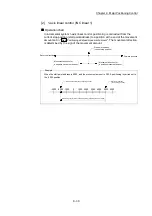
POINT
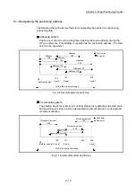
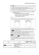
When the "reference axis speed" is set during interpolation control, set so the major
axis side becomes the reference axis. If the minor axis side is set as the reference
axis, the major axis side speed may exceed the "
Pr.8
Speed limit value
".
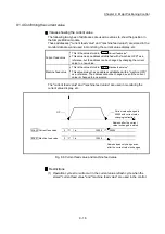
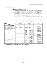
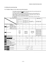
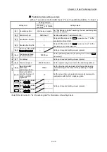
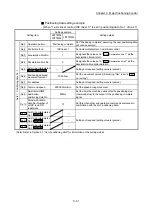
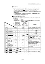
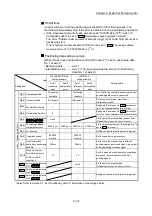
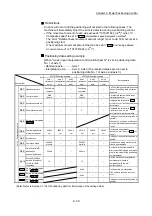
Limits to interpolation control
There are limits to the interpolation control that can be executed and speed (
Pr.20
Interpolation speed designation method
) that can be set, depending on the "
Pr.1
Unit
setting
" of the reference axis and interpolation axis. (For example, circular
interpolation control cannot be executed if the reference axis and interpolation axis
units differ.)
The following table shows the interpolation control and speed designation limits.
"
Da.2
Control method
"
interpolation control
Pr.20
Interpolation speed
designation method
Pr.1
Unit setting
1
Reference axis and interpolation
axis units are the same, or a
combination of "mm" and "inch".
3
Reference axis and
interpolation axis units
differ 3
Linear 2 (ABS, INC)
Fixed-feed 2
Composite speed
Reference axis speed
Circular sub (ABS, INC)
Circular right (ABS, INC)
Circular left (ABS, INC)
Composite speed
2
Reference axis speed
Linear 3 (ABS, INC)
Fixed-feed 3
Composite speed
Reference axis speed
Linear 4 (ABS, INC)
Fixed-feed 4
Composite speed
Reference axis speed
: Setting possible, : Setting not possible.
1: "mm" and "inch" unit mix possible.
When "mm" and "inch" are mixed, convert as follows for the positioning.
•
If interpolation control units are "mm", positioning is controlled by calculating position commands from the address,
travel value, positioning speed and electronic gear, which have been converted to "mm" using the formula: inch
setting value 25.4 = mm setting value.
•
If interpolation control units are "inch", positioning is controlled by calculating position commands from the address,
travel value, positioning speed and electronic gear, which have been converted to "inch" using the formula: mm
setting value 25.4 = inch setting value.
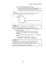
2: "degree" setting not possible. The error "Circular interpolation not possible" (error code: 535) will occur and the
positioning control does not start if circular interpolation control is set when the unit is "degree". The machine will
carry out a deceleration
stop if "degree" is set during positioning control.
3: The unit set in the reference axis will be used for the speed unit during control if the units differ or if "mm" and "inch"
are combined.
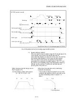
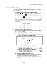
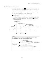
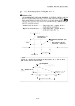
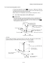
Axis operation status during interpolation control
"Interpolation" will be stored in the "
Md.26
Axis operation status
" during interpolation
control. "Standby" will be stored when the interpolation operation is terminated.
Both the reference axis and interpolation axis will carry out a deceleration stop if
an error occurs during control, and "Error" will be stored in the operation status.
Содержание MELSEC-L Series
Страница 1: ...MELSEC L LD77MS Simple Motion Module User s Manual Positioning Control LD77MS2 LD77MS4 LD77MS16 ...
Страница 2: ......
Страница 30: ...MEMO ...
Страница 70: ...2 10 Chapter 2 System Configuration MEMO ...
Страница 83: ...3 13 Chapter 3 Specifications and Functions MEMO ...
Страница 103: ...3 33 Chapter 3 Specifications and Functions MEMO ...
Страница 107: ...3 37 Chapter 3 Specifications and Functions MEMO ...
Страница 111: ...3 41 Chapter 3 Specifications and Functions MEMO ...
Страница 115: ...3 45 Chapter 3 Specifications and Functions MEMO ...
Страница 140: ...4 22 Chapter 4 Installation Wiring and Maintenance of the Product MEMO ...
Страница 253: ...5 113 Chapter 5 Data Used for Positioning Control MEMO ...
Страница 342: ...5 202 Chapter 5 Data Used for Positioning Control MEMO ...
Страница 438: ...7 20 Chapter 7 Memory Configuration and Data Process MEMO ...
Страница 440: ...MEMO ...
Страница 485: ...9 25 Chapter 9 Major Positioning Control MEMO ...
Страница 594: ...9 134 Chapter 9 Major Positioning Control MEMO ...
Страница 624: ...10 30 Chapter 10 High Level Positioning Control MEMO ...
Страница 656: ...11 32 Chapter 11 Manual Control MEMO ...
Страница 690: ...12 34 Chapter 12 Expansion Control MEMO ...
Страница 798: ...13 108 Chapter 13 Control Sub Functions MEMO ...
Страница 866: ...14 68 Chapter 14 Common Functions MEMO ...
Страница 884: ...15 18 Chapter 15 Dedicated Instructions MEMO ...
Страница 899: ...16 15 Chapter 16 Troubleshooting MEMO ...
Страница 1036: ...Appendix 88 Appendices MEMO ...
Страница 1039: ......


