


3 - 26
Chapter 3 Specifications and Functions
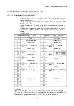
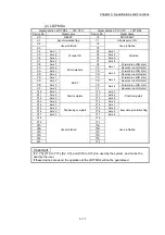
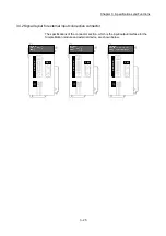
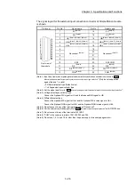
The signal layout for the external input connection connector of Simple Motion module
is shown.
Pin layout
Pin No.
Signal name
Pin No.
Signal name
1
12
11
10
9
8
7
6
5
4
3
2
14
26
25
24
23
22
21
20
19
18
17
16
15
Front view of
the module
13
1
5V
(Note-9)
14
5V
(Note-9)
2
SG
(Note-9)
15
SG
(Note-9)
3
HA
(Note-1), (Note-2), (Note-3)
16
HB
(Note-1), (Note-2), (Note-3)
4
HAH
(Note-1), (Note-2), (Note-4)
17
HBH
(Note-1), (Note-2), (Note-4)
5
HAL
(Note-1), (Note-2), (Note-4)
18
HBL
(Note-1), (Note-2), (Note-4)
6
No connect
(Note-5)
19
No connect
(Note-5)
7 20
8 21
9 22
10 EMI 23
EMI.
COM
11
DI1
(Note-6)
24
DI2
(Note-6)
12
DI3
(Note-6), (Note-7)
25
DI4
(Note-6), (Note-7)
13
COM
(Note-8)
26
COM
(Note-8)
(Note-1): Input type from manual pulse generator/incremental synchronous encoder is switched in "
Pr.89
Manual pulse generator/Incremental synchronous encoder input type selection
". (Only the value specified
against the axis 1 is valid.)
• 0: Differential-output type (Default value)
• 1: Voltage-output/open-collector type
(Note-2): Set the signal input form in "
Pr.24
Manual pulse generator/Incremental synchronous encoder input selection
".
(Note-3): Voltage-output/open-collector type
Connect the A-phase/PLS signal to HA, and the B-phase/SIGN signal to HB.
(Note-4): Differential-output type
Connect the A-phase/PLS signal to HAH, and the A-phase/PLS inverse signal to HAL.
Connect the B-phase/SIGN signal to HBH, and the B-phase/SIGN inverse signal to HBL.
(Note-5): Do not connect to any of the terminal explained as "No connect".
(Note-6): Set the external command signal [DI] in "
Pr.95
External command signal selection
" at LD77MS16 use.
(Note-7): Do not connect to any of the terminal at LD77MS2.
(Note-8): "COM" is the common terminal of DI1, DI2, DI3 and DI4.
(Note-9): Do not use 1, 2, 14 and 15 for other than the power supply of manual pulse generator.
Содержание MELSEC-L Series
Страница 1: ...MELSEC L LD77MS Simple Motion Module User s Manual Positioning Control LD77MS2 LD77MS4 LD77MS16 ...
Страница 2: ......
Страница 30: ...MEMO ...
Страница 70: ...2 10 Chapter 2 System Configuration MEMO ...
Страница 83: ...3 13 Chapter 3 Specifications and Functions MEMO ...
Страница 103: ...3 33 Chapter 3 Specifications and Functions MEMO ...
Страница 107: ...3 37 Chapter 3 Specifications and Functions MEMO ...
Страница 111: ...3 41 Chapter 3 Specifications and Functions MEMO ...
Страница 115: ...3 45 Chapter 3 Specifications and Functions MEMO ...
Страница 140: ...4 22 Chapter 4 Installation Wiring and Maintenance of the Product MEMO ...
Страница 253: ...5 113 Chapter 5 Data Used for Positioning Control MEMO ...
Страница 342: ...5 202 Chapter 5 Data Used for Positioning Control MEMO ...
Страница 438: ...7 20 Chapter 7 Memory Configuration and Data Process MEMO ...
Страница 440: ...MEMO ...
Страница 485: ...9 25 Chapter 9 Major Positioning Control MEMO ...
Страница 594: ...9 134 Chapter 9 Major Positioning Control MEMO ...
Страница 624: ...10 30 Chapter 10 High Level Positioning Control MEMO ...
Страница 656: ...11 32 Chapter 11 Manual Control MEMO ...
Страница 690: ...12 34 Chapter 12 Expansion Control MEMO ...
Страница 798: ...13 108 Chapter 13 Control Sub Functions MEMO ...
Страница 866: ...14 68 Chapter 14 Common Functions MEMO ...
Страница 884: ...15 18 Chapter 15 Dedicated Instructions MEMO ...
Страница 899: ...16 15 Chapter 16 Troubleshooting MEMO ...
Страница 1036: ...Appendix 88 Appendices MEMO ...
Страница 1039: ......


