


4 - 11
Chapter 4 Installation, Wiring and Maintenance of the Product
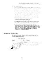
[1] Precautions for wiring
(1) Use separate cables for connecting to the Simple Motion module and for the
power cable that create surge and inductance.
(2) The cable for connecting the Simple Motion module can be placed in the
duct or secured in place by clamps. If the cable is not placed in the duct or
secured by clamps, unevenness or movement of the cable or careless
pulling on it could result in damage to the unit or cable or defective cable
connections could cause mis-operation of the unit.
(3) If a duct is being used, separate the cables to connect the Simple Motion
module from the power line duct, or use metal piping.
Ground the pipes securely after metal piping.
(4) Use the twisted pair shielded cable (wire size AWG30 to AWG24 (0.05 to
0.2 mm
2
)). The shielded must be grounded in the cable connector shell.
(5) Use separate shielded cables of the forced stop input signal (EMI,
EMI.COM), external command signal/switching signal (DI1, DI2, DI3, DI4,
COM), and manual pulse generator/incremental synchronous encoder input
signal (HAH, HAL, HBH, HBL, HA, HB, 5V, SG) for connecting to the Simple
Motion module. They can cause electrical interference, surges and
inductance that can lead to mis-operation.
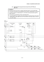
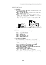
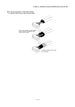
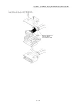
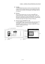
[Wiring example of shielded cable]
The following shows a wiring example for noise reduction in the case when the
connector (LD77MHIOCON) is used.
To the Simple Motion module
Connector
(LD77MHIOCON)
The shield must be grounded in the cable connector shell.
For manual pulse generator
/Incremental synchronous encoder input signal
For forced stop input signal
/External command signal/Switching signal
Shielded cable
Содержание MELSEC-L Series
Страница 1: ...MELSEC L LD77MS Simple Motion Module User s Manual Positioning Control LD77MS2 LD77MS4 LD77MS16 ...
Страница 2: ......
Страница 30: ...MEMO ...
Страница 70: ...2 10 Chapter 2 System Configuration MEMO ...
Страница 83: ...3 13 Chapter 3 Specifications and Functions MEMO ...
Страница 103: ...3 33 Chapter 3 Specifications and Functions MEMO ...
Страница 107: ...3 37 Chapter 3 Specifications and Functions MEMO ...
Страница 111: ...3 41 Chapter 3 Specifications and Functions MEMO ...
Страница 115: ...3 45 Chapter 3 Specifications and Functions MEMO ...
Страница 140: ...4 22 Chapter 4 Installation Wiring and Maintenance of the Product MEMO ...
Страница 253: ...5 113 Chapter 5 Data Used for Positioning Control MEMO ...
Страница 342: ...5 202 Chapter 5 Data Used for Positioning Control MEMO ...
Страница 438: ...7 20 Chapter 7 Memory Configuration and Data Process MEMO ...
Страница 440: ...MEMO ...
Страница 485: ...9 25 Chapter 9 Major Positioning Control MEMO ...
Страница 594: ...9 134 Chapter 9 Major Positioning Control MEMO ...
Страница 624: ...10 30 Chapter 10 High Level Positioning Control MEMO ...
Страница 656: ...11 32 Chapter 11 Manual Control MEMO ...
Страница 690: ...12 34 Chapter 12 Expansion Control MEMO ...
Страница 798: ...13 108 Chapter 13 Control Sub Functions MEMO ...
Страница 866: ...14 68 Chapter 14 Common Functions MEMO ...
Страница 884: ...15 18 Chapter 15 Dedicated Instructions MEMO ...
Страница 899: ...16 15 Chapter 16 Troubleshooting MEMO ...
Страница 1036: ...Appendix 88 Appendices MEMO ...
Страница 1039: ......


