


9 - 21
Chapter 9 Major Positioning Control
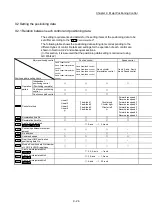
9.1.6 Interpolation control
Meaning of interpolation control
In "2-axis linear interpolation control", "3-axis linear interpolation control", "4-axis
linear interpolation control", "2-axis fixed-feed control", "3-axis fixed-feed control",
"4-axis fixed-feed control", "2-axis speed control", "3-axis speed control", "4-axis
speed control", and "2-axis circular interpolation control", control is carried out so
that linear and arc paths are drawn using a motor set in two to four axis directions.
This kind of control is called "interpolation control".
In interpolation control, the axis in which the control method is set is defined as the
"reference axis", and the other axis is defined as the "interpolation axis".
The Simple Motion module controls the "reference axis" following the positioning
data set in the "reference axis", and controls the "interpolation axis" corresponding
to the reference axis control so that a linear or arc path is drawn.
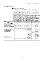
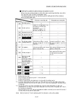
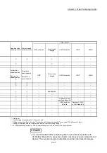
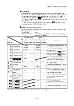
The following table shows the reference axis and interpolation axis combinations.
Axis definition
Interpolation of
"
Da.2 Control method"
LD77MS2 LD77MS4 LD77MS16
Reference
axis
Interpolation
axis
Reference
axis
Interpolation
axis
Reference
axis
Interpolation
axis
2-axis linear interpolation control
2-axis fixed-feed control
2-axis circular interpolation control
2-axis speed control
Any of
axes
1 to 2
"Axis to be
interpolated" set
in reference axis
Any of
axes
1 to 4
"Axis to be
interpolated" set
in reference axis
Any of
axes
1 to 16
"Axis to be
interpolated
No.1" set in
reference axis
3-axis linear interpolation control
3-axis fixed-feed control
3-axis speed control
–
Axis 1
Axis 2, Axis 3
"Axis to be
interpolated
No.1" and "Axis
to be
interpolated
No.2" set in
reference axis
–
Axis 2
Axis 3, Axis 4
–
Axis 3
Axis 4, Axis 1
–
Axis 4
Axis 1, Axis 2
4-axis linear interpolation control
4-axis fixed-feed control
4-axis speed control
– Axis
1
Axis 2, Axis 3,
Axis 4
"Axis to be
interpolated
No.1", "Axis to
be interpolated
No.2" and "Axis
to be
interpolated
No.3" set in
reference axis
– Axis
2
Axis 3, Axis 4,
Axis 1
– Axis
3
Axis 4, Axis 1,
Axis 2
– Axis
4
Axis 1, Axis 2,
Axis 3
– : Setting not required (Use the initial value or a value within the setting range.)
Содержание MELSEC-L Series
Страница 1: ...MELSEC L LD77MS Simple Motion Module User s Manual Positioning Control LD77MS2 LD77MS4 LD77MS16 ...
Страница 2: ......
Страница 30: ...MEMO ...
Страница 70: ...2 10 Chapter 2 System Configuration MEMO ...
Страница 83: ...3 13 Chapter 3 Specifications and Functions MEMO ...
Страница 103: ...3 33 Chapter 3 Specifications and Functions MEMO ...
Страница 107: ...3 37 Chapter 3 Specifications and Functions MEMO ...
Страница 111: ...3 41 Chapter 3 Specifications and Functions MEMO ...
Страница 115: ...3 45 Chapter 3 Specifications and Functions MEMO ...
Страница 140: ...4 22 Chapter 4 Installation Wiring and Maintenance of the Product MEMO ...
Страница 253: ...5 113 Chapter 5 Data Used for Positioning Control MEMO ...
Страница 342: ...5 202 Chapter 5 Data Used for Positioning Control MEMO ...
Страница 438: ...7 20 Chapter 7 Memory Configuration and Data Process MEMO ...
Страница 440: ...MEMO ...
Страница 485: ...9 25 Chapter 9 Major Positioning Control MEMO ...
Страница 594: ...9 134 Chapter 9 Major Positioning Control MEMO ...
Страница 624: ...10 30 Chapter 10 High Level Positioning Control MEMO ...
Страница 656: ...11 32 Chapter 11 Manual Control MEMO ...
Страница 690: ...12 34 Chapter 12 Expansion Control MEMO ...
Страница 798: ...13 108 Chapter 13 Control Sub Functions MEMO ...
Страница 866: ...14 68 Chapter 14 Common Functions MEMO ...
Страница 884: ...15 18 Chapter 15 Dedicated Instructions MEMO ...
Страница 899: ...16 15 Chapter 16 Troubleshooting MEMO ...
Страница 1036: ...Appendix 88 Appendices MEMO ...
Страница 1039: ......


