


13 - 14
Chapter 13 Control Sub Functions
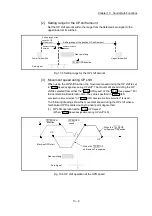
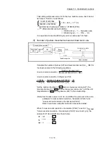
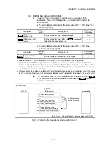
[1] Basic concept of the electronic gear
The electronic gear is an item which determines how many rotations (rotations by
how many pulses) the motor must make in order to move the machine according
to the programmed movement amount.
M
ENC
PLS
Servo
amplifier
PLS
Feedback pulse
Command
value
PLS
Control
unit
Simple Motion module
Machine
Reduction ratio
AP
AL AM
The basic concept of the electronic gear is represented by the following
expression.
Pr.2
(Number of pulses per rotation) = AP
Pr.3
(Movement amount per rotation) = AL
Pr.4
(Unit magnification)
= AM
Movement amount per rotation that considered unit magnification =
S
Electronic gear =
AP
=
AP
…(1)
S
AL
AM
Set values for AP, AL and AM so that this related equation is established.
However, because values to be set for AP, AL and AM have the settable range,
values calculated (reduced) from the above related equation must be contained
in the setting range for AP, AL and AM.
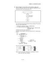
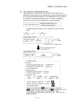
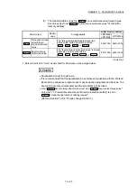
(1) For "Ball screw" + "Reduction gear"
When the ball screw pitch is 10mm, the motor is the HG-KR (4194304
PLS/rev) and the reduction ratio of the reduction gear is 9/44.
M
Machine
Reduction ratio 9/44
First, find how many millimeters the load (machine) will travel (
S
) when
the motor turns one revolution (AP).
AP (Number of pulses per rotation) = 4194304 [PLS]
S
(Movement amount per rotation)
= Ball screw pitch
Reduction ratio
= 10 [mm]
9/44
= 10000.0 [
m]
9/44
When the control unit is
"mm", the minimum
command unit is 0.1
μ
m.
Содержание MELSEC-L Series
Страница 1: ...MELSEC L LD77MS Simple Motion Module User s Manual Positioning Control LD77MS2 LD77MS4 LD77MS16 ...
Страница 2: ......
Страница 30: ...MEMO ...
Страница 70: ...2 10 Chapter 2 System Configuration MEMO ...
Страница 83: ...3 13 Chapter 3 Specifications and Functions MEMO ...
Страница 103: ...3 33 Chapter 3 Specifications and Functions MEMO ...
Страница 107: ...3 37 Chapter 3 Specifications and Functions MEMO ...
Страница 111: ...3 41 Chapter 3 Specifications and Functions MEMO ...
Страница 115: ...3 45 Chapter 3 Specifications and Functions MEMO ...
Страница 140: ...4 22 Chapter 4 Installation Wiring and Maintenance of the Product MEMO ...
Страница 253: ...5 113 Chapter 5 Data Used for Positioning Control MEMO ...
Страница 342: ...5 202 Chapter 5 Data Used for Positioning Control MEMO ...
Страница 438: ...7 20 Chapter 7 Memory Configuration and Data Process MEMO ...
Страница 440: ...MEMO ...
Страница 485: ...9 25 Chapter 9 Major Positioning Control MEMO ...
Страница 594: ...9 134 Chapter 9 Major Positioning Control MEMO ...
Страница 624: ...10 30 Chapter 10 High Level Positioning Control MEMO ...
Страница 656: ...11 32 Chapter 11 Manual Control MEMO ...
Страница 690: ...12 34 Chapter 12 Expansion Control MEMO ...
Страница 798: ...13 108 Chapter 13 Control Sub Functions MEMO ...
Страница 866: ...14 68 Chapter 14 Common Functions MEMO ...
Страница 884: ...15 18 Chapter 15 Dedicated Instructions MEMO ...
Страница 899: ...16 15 Chapter 16 Troubleshooting MEMO ...
Страница 1036: ...Appendix 88 Appendices MEMO ...
Страница 1039: ......


