


11 - 26
Chapter 11 Manual Control
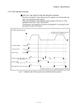
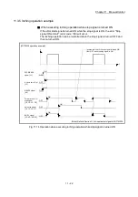
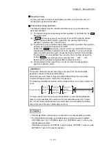
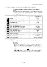
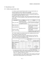
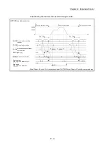
Operations when stroke limit error occurs
When the hardware stroke limit error or the software stroke limit error is detected
(Note-1)
during operation, the operation will decelerate to a stop. However, in case
of "
Md.26
Axis operation status
", "Manual pulse generator operation" will continue
(Note-1)
. After stopping, input pulses from a manual pulse generator to the outside
direction of the limit range are not accepted, but operation can be executed within
the range.
(Note-1): Only when the current feed value or the machine feed value overflows or
underflows during deceleration, the manual pulse generator operation will
terminate as "error occurring". To carry out manual pulse generator operation
again, "
Cd.21
Manual pulse generator enable flag
" must be turned OFF once and
turn ON.
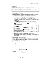
Upper/lower
limit signal
Manual pulse generator
operation possible
Manual pulse generator
operation not possible
V
Manual pulse
generator operation
ON
OFF
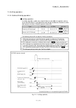
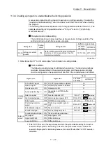
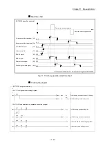
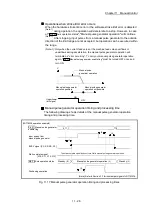
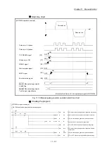
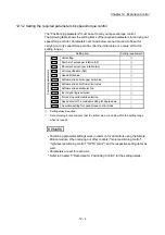
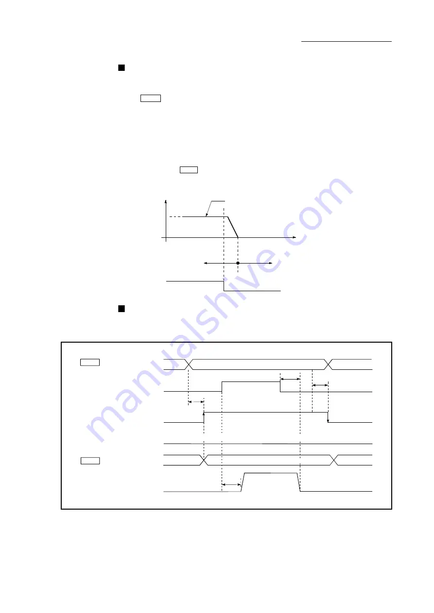
Manual pulse generator operation timing and processing time
The following drawing shows details of the manual pulse generator operation
timing and processing time.
[LD77MS4 operation example]
Input pulses from
manual pulse generator
t1
t3
t4
BUSY signal [XC, XD, XE, XF]
Standby (0)
Start complete signal
[X10, X11, X12, X13]
Positioning operation
The start complete signal does not turn ON in manual pulse generator operation.
0
0
1
Cd. 21 Manual pulse generator
enable flag
Md. 26 Axis operation status
Standby
(0)
Manual pulse generator operation
(4)
t2
(Note): Refer to Section 3.3 for input/output signal of LD77MS16.
Fig. 11.17 Manual pulse generator operation timing and processing times
Содержание MELSEC-L Series
Страница 1: ...MELSEC L LD77MS Simple Motion Module User s Manual Positioning Control LD77MS2 LD77MS4 LD77MS16 ...
Страница 2: ......
Страница 30: ...MEMO ...
Страница 70: ...2 10 Chapter 2 System Configuration MEMO ...
Страница 83: ...3 13 Chapter 3 Specifications and Functions MEMO ...
Страница 103: ...3 33 Chapter 3 Specifications and Functions MEMO ...
Страница 107: ...3 37 Chapter 3 Specifications and Functions MEMO ...
Страница 111: ...3 41 Chapter 3 Specifications and Functions MEMO ...
Страница 115: ...3 45 Chapter 3 Specifications and Functions MEMO ...
Страница 140: ...4 22 Chapter 4 Installation Wiring and Maintenance of the Product MEMO ...
Страница 253: ...5 113 Chapter 5 Data Used for Positioning Control MEMO ...
Страница 342: ...5 202 Chapter 5 Data Used for Positioning Control MEMO ...
Страница 438: ...7 20 Chapter 7 Memory Configuration and Data Process MEMO ...
Страница 440: ...MEMO ...
Страница 485: ...9 25 Chapter 9 Major Positioning Control MEMO ...
Страница 594: ...9 134 Chapter 9 Major Positioning Control MEMO ...
Страница 624: ...10 30 Chapter 10 High Level Positioning Control MEMO ...
Страница 656: ...11 32 Chapter 11 Manual Control MEMO ...
Страница 690: ...12 34 Chapter 12 Expansion Control MEMO ...
Страница 798: ...13 108 Chapter 13 Control Sub Functions MEMO ...
Страница 866: ...14 68 Chapter 14 Common Functions MEMO ...
Страница 884: ...15 18 Chapter 15 Dedicated Instructions MEMO ...
Страница 899: ...16 15 Chapter 16 Troubleshooting MEMO ...
Страница 1036: ...Appendix 88 Appendices MEMO ...
Страница 1039: ......


