


8 - 14
Chapter 8 OPR Control
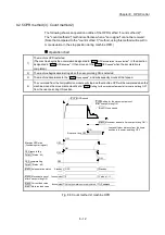
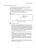
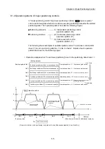
8.2.6 OPR method (4): Data set method
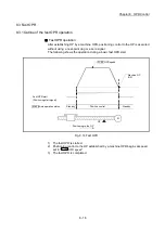
The following shows an operation outline of the OPR method "data set method".
The "Data set method" method is effective when a "Near-point dog" is not used.
It can be used with absolute position system.
With the data set method OPR, the position where the machine OPR has been carried
out, is registered into the Simple Motion module as the OP, and the current feed value
and feed machine value is overwritten to an OP address.
Use the JOG or manual pulse generator operation to move the OP.
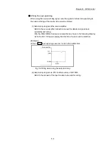
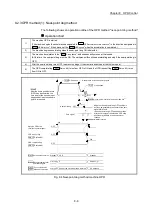
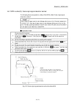
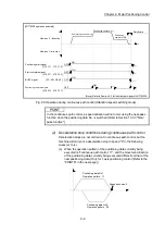
Operation chart
OPR start
The address upon execution
of the OPR is registered as
an OP address.
t
Fig. 8.10 Data set method OPR
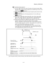
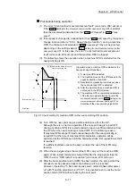
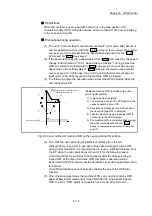
Precautions during operation
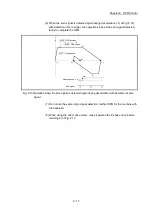
(1) The zero point must have been passed before the OPR is carried out after the
power supply is turned ON. If the OPR is carried out without passing the zero
point even once, the error "OPR zero point not passed" (error code: 210) will
occur. When the error "OPR zero point not passed" (error code: 210) occurs,
perform the JOG or similar operation so that the servomotor makes more than
one revolution after an error reset, before carrying out the machine OPR again.
However, if selecting "1: Not need to pass servo motor Z-phase after power
on" with "Function selection C-4 (PC17)", it is possible to carry out the home
position return (OPR) without passing the zero point.
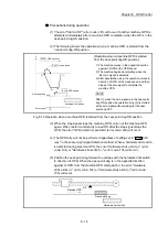
(2) The OPR data used for the data set method is the "OPR direction" and "OP
address".
The OPR data other than that for the OPR direction and OP address is not
used for the data set method OPR method, but if a value is set the outside the
setting range, an error will occur when the PLC READY signal [Y0] is turned
ON so that the READY signal [X0] is not turned OFF.
With the OPR data other than that for the OPR direction and OP address, set
an arbitrary value (default value can be allowed) within each data setting
range so that an error will not occur upon receiving the PLC READY signal
[Y0] ON.
(3) When using the backlash compensation function, set the same movement
direction of the JOG or manual pulse generator operation to the OP before the
OPR is executed as "OPR direction".
Содержание MELSEC-L Series
Страница 1: ...MELSEC L LD77MS Simple Motion Module User s Manual Positioning Control LD77MS2 LD77MS4 LD77MS16 ...
Страница 2: ......
Страница 30: ...MEMO ...
Страница 70: ...2 10 Chapter 2 System Configuration MEMO ...
Страница 83: ...3 13 Chapter 3 Specifications and Functions MEMO ...
Страница 103: ...3 33 Chapter 3 Specifications and Functions MEMO ...
Страница 107: ...3 37 Chapter 3 Specifications and Functions MEMO ...
Страница 111: ...3 41 Chapter 3 Specifications and Functions MEMO ...
Страница 115: ...3 45 Chapter 3 Specifications and Functions MEMO ...
Страница 140: ...4 22 Chapter 4 Installation Wiring and Maintenance of the Product MEMO ...
Страница 253: ...5 113 Chapter 5 Data Used for Positioning Control MEMO ...
Страница 342: ...5 202 Chapter 5 Data Used for Positioning Control MEMO ...
Страница 438: ...7 20 Chapter 7 Memory Configuration and Data Process MEMO ...
Страница 440: ...MEMO ...
Страница 485: ...9 25 Chapter 9 Major Positioning Control MEMO ...
Страница 594: ...9 134 Chapter 9 Major Positioning Control MEMO ...
Страница 624: ...10 30 Chapter 10 High Level Positioning Control MEMO ...
Страница 656: ...11 32 Chapter 11 Manual Control MEMO ...
Страница 690: ...12 34 Chapter 12 Expansion Control MEMO ...
Страница 798: ...13 108 Chapter 13 Control Sub Functions MEMO ...
Страница 866: ...14 68 Chapter 14 Common Functions MEMO ...
Страница 884: ...15 18 Chapter 15 Dedicated Instructions MEMO ...
Страница 899: ...16 15 Chapter 16 Troubleshooting MEMO ...
Страница 1036: ...Appendix 88 Appendices MEMO ...
Страница 1039: ......


