


16 - 25
Chapter 16 Troubleshooting
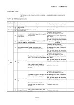
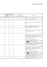
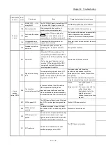
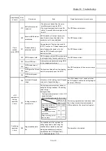
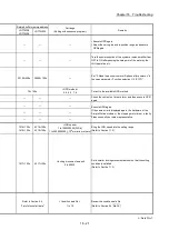
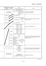
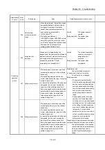
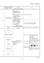
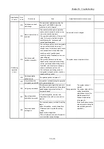
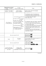
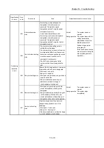
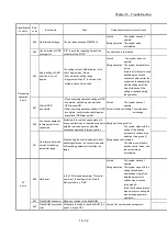
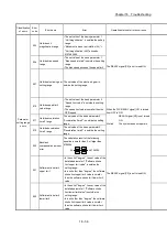
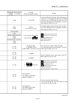
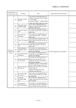
Related buffer memory address
Set range
(Setting with sequence program)
Remedy
LD77MS2
LD77MS4
LD77MS16
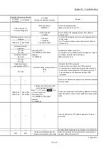
Refer to Section 5.3
"List of positioning data"
<Positioning address/movement amount>
• ABS
unit [mm] [inch] [PLS]
–2147483648 to 2147483647
Unit [degree] 0 to 35999999
• INC
(When software stroke limits are valid)
Unit [mm], [inch] [PLS]:
–2147483648 to 2147483647
Unit [degree]:
–35999999 to 35999999
(When software stroke limits are invalid)
–2147483648 to 2147483647
• Speed-position switching
INC mode: 0 to 2147483647
ABS mode: 0 to 35999999
([degree] only)
• Position-speed switching
0 to 2147483647
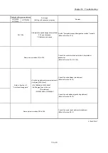
<Arc address>
–2147483648 to 2147483647
Review the positioning address.
• Correct the center point address (arc address)
• Correct the end address (positioning address)
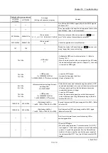
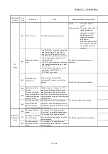
60+150n
61+150n
<Circular interpolation error allowable limit>
0 to 1000000
Correct the circular interpolation error allowable limit value.
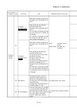
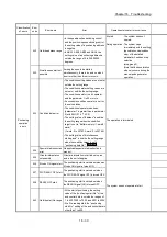
New current value
<New current value>
<Software stroke upper and lower limits>
• [mm] [inch] [PLS]
–2147483648 to 2147483647
• [degree]
0 to 35999999
At operation start : • Set the current feed value within the
software stroke limit by the manual
control operation.
(Refer to Chapter 11)
• Correct the positioning address. (At
circular interpolation with sub points
designated, also check the arc address.)
New current value : Set the new current value within the
software stroke limit. (Refer to Section
9.2.19)
During operation : Correct the positioning address.
(For the positioning and arc addresses,
refer to
Da.6
and
Da.7
in Section 5.3)
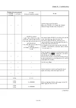
At speed control mode/torque control mode/continuous
operation to torque control mode:
Review the operation so that the current
feed value does not exceed the software
stroke limit.
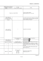
1506+100n
1507+100n
4306+100n
4307+100n
Software stroke limit
upper limit
18+150n
19+150n
Software stroke limit
lower limit
20+150n
21+150n
n: Axis No.-1
Содержание MELSEC-L Series
Страница 1: ...MELSEC L LD77MS Simple Motion Module User s Manual Positioning Control LD77MS2 LD77MS4 LD77MS16 ...
Страница 2: ......
Страница 30: ...MEMO ...
Страница 70: ...2 10 Chapter 2 System Configuration MEMO ...
Страница 83: ...3 13 Chapter 3 Specifications and Functions MEMO ...
Страница 103: ...3 33 Chapter 3 Specifications and Functions MEMO ...
Страница 107: ...3 37 Chapter 3 Specifications and Functions MEMO ...
Страница 111: ...3 41 Chapter 3 Specifications and Functions MEMO ...
Страница 115: ...3 45 Chapter 3 Specifications and Functions MEMO ...
Страница 140: ...4 22 Chapter 4 Installation Wiring and Maintenance of the Product MEMO ...
Страница 253: ...5 113 Chapter 5 Data Used for Positioning Control MEMO ...
Страница 342: ...5 202 Chapter 5 Data Used for Positioning Control MEMO ...
Страница 438: ...7 20 Chapter 7 Memory Configuration and Data Process MEMO ...
Страница 440: ...MEMO ...
Страница 485: ...9 25 Chapter 9 Major Positioning Control MEMO ...
Страница 594: ...9 134 Chapter 9 Major Positioning Control MEMO ...
Страница 624: ...10 30 Chapter 10 High Level Positioning Control MEMO ...
Страница 656: ...11 32 Chapter 11 Manual Control MEMO ...
Страница 690: ...12 34 Chapter 12 Expansion Control MEMO ...
Страница 798: ...13 108 Chapter 13 Control Sub Functions MEMO ...
Страница 866: ...14 68 Chapter 14 Common Functions MEMO ...
Страница 884: ...15 18 Chapter 15 Dedicated Instructions MEMO ...
Страница 899: ...16 15 Chapter 16 Troubleshooting MEMO ...
Страница 1036: ...Appendix 88 Appendices MEMO ...
Страница 1039: ......


