

12 - 10
Chapter 12 Expansion Control
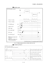
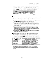
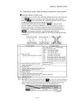
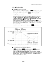
Operation for "Position control mode
↔
Torque control mode switching"
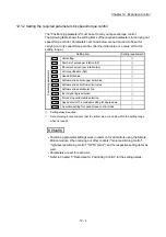
When the position control mode is switched to the torque control mode, the
command torque immediately after the switching is the torque set in "Torque initial
value selection (b4 to b7)" of "
Pr.90
Operation setting for speed-torque control mode
".
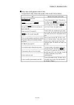
Torque initial value selection
(
Pr.90
: b4 to b7)
Command torque to servo amplifier immediately after switching from
position control mode to torque control mode
0: Command torque
The value of "
Cd.143
Command torque at torque control mode
" at
switching.
1: Feedback torque
Motor torque value at switching.
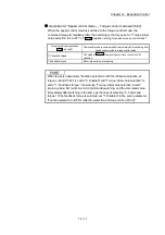
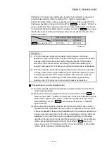
POINT
When the servo parameter "Function selection C-B POL reflection selection at
torque control (PC29)" is set to "0: Enabled" and "Torque initial value selection" is
set to "1: Feedback torque", the warning "Torque initial value selection invalid"
(warning code: 521) will occur at control mode switching, and the command value
immediately after switching is the same as the case of selecting "0: Command
torque". If the feedback torque is selected, set "1: Disabled" in the servo parameter
"Function selection C-B POL reflection selection at torque control (PC29)".
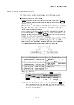
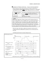
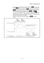
When the torque control mode is switched to the position control mode, the
command position immediately after the switching is the current feed value at
switching.
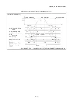
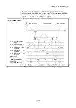
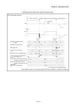
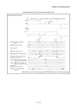
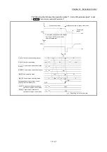
The following chart shows the operation timing for axis 1.
[LD77MS4 operation example]
0
1
0
1
0
0
20
0
0
200
0
300
0
32
30
30
0
[0, 0]
OFF
ON
[0, 1]
[0, 0]
t
30.0%
20.0%
50000
0
ON
OFF
Torque
Position control mode
Torque control mode
Position control mode
6 to 11ms
6 to 11ms
BUSY signal [XC]
Axis operation status
Md.26
Cd.146 Speed limit value at torque
control mode
Cd.143 Command torque at torque
control mode
Cd.138 Control mode switching
request
Cd.139 Control mode setting
Zero speed
( Servo status: b3)
Md.108
Control mode
( Servo status: b2, b3)
Md.108
0
(Note): Refer to Section 3.3 for input/output signal of LD77MS16 and Chapter 5 for buffer memory address.
Содержание MELSEC-L Series
Страница 1: ...MELSEC L LD77MS Simple Motion Module User s Manual Positioning Control LD77MS2 LD77MS4 LD77MS16 ...
Страница 2: ......
Страница 30: ...MEMO ...
Страница 70: ...2 10 Chapter 2 System Configuration MEMO ...
Страница 83: ...3 13 Chapter 3 Specifications and Functions MEMO ...
Страница 103: ...3 33 Chapter 3 Specifications and Functions MEMO ...
Страница 107: ...3 37 Chapter 3 Specifications and Functions MEMO ...
Страница 111: ...3 41 Chapter 3 Specifications and Functions MEMO ...
Страница 115: ...3 45 Chapter 3 Specifications and Functions MEMO ...
Страница 140: ...4 22 Chapter 4 Installation Wiring and Maintenance of the Product MEMO ...
Страница 253: ...5 113 Chapter 5 Data Used for Positioning Control MEMO ...
Страница 342: ...5 202 Chapter 5 Data Used for Positioning Control MEMO ...
Страница 438: ...7 20 Chapter 7 Memory Configuration and Data Process MEMO ...
Страница 440: ...MEMO ...
Страница 485: ...9 25 Chapter 9 Major Positioning Control MEMO ...
Страница 594: ...9 134 Chapter 9 Major Positioning Control MEMO ...
Страница 624: ...10 30 Chapter 10 High Level Positioning Control MEMO ...
Страница 656: ...11 32 Chapter 11 Manual Control MEMO ...
Страница 690: ...12 34 Chapter 12 Expansion Control MEMO ...
Страница 798: ...13 108 Chapter 13 Control Sub Functions MEMO ...
Страница 866: ...14 68 Chapter 14 Common Functions MEMO ...
Страница 884: ...15 18 Chapter 15 Dedicated Instructions MEMO ...
Страница 899: ...16 15 Chapter 16 Troubleshooting MEMO ...
Страница 1036: ...Appendix 88 Appendices MEMO ...
Страница 1039: ......


