


13 - 67
Chapter 13 Control Sub Functions
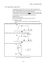
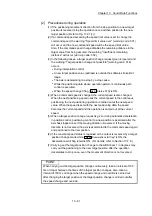
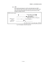
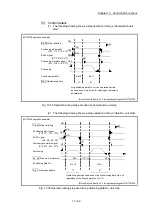
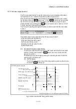
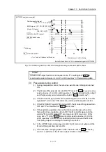
[2] Step mode
In step operations, the timing for stopping the control can be set. This is called
the "step mode". (The "step mode" is set in the control data "
Cd.34
Step mode
".)
The following shows the two types of "step mode" functions.
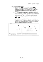
(1) Deceleration unit step
The operation stops at positioning data requiring automatic deceleration. (A
normal operation will be carried out until the positioning data requiring
automatic deceleration is found. Once found, that positioning data will be
executed, and the operation will then automatically decelerate and stop.)
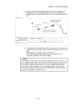
(2) Data No. unit step
The operation automatically decelerates and stops for each positioning
data. (Even in continuous path control, an automatic deceleration and stop
will be forcibly carried out.)
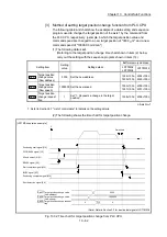
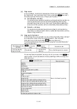
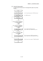
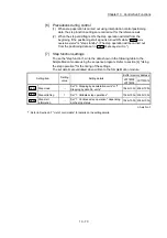
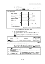
[3] Step start information
Control stopped by a step operation can be continued by setting "step continues"
(to continue the control) in the "step start information". (The "step start
information" is set in the control data "
Cd.36
Step start information
".)
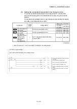
The following table shows the results of starts using the "step start information"
during step operation.
Stop status in the step
operation
Md.26
Axis operation
status
Cd.36
Step start
information
Step start results
1 step of positioning
stopped normally
Step standby
1: Continues step
operation
The next positioning data is executed.
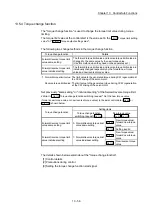
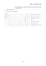
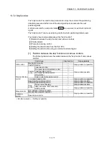
The warning "Step not possible" (warning code: 511) will occur if the "
Md.26
Axis
operation status
" is as shown below or the step valid flag is OFF when step start
information is set.
Md.26
Axis operation status
Step start results
Standby
Step not continued by warning
Stopped
Interpolation
JOG operation
Manual pulse generator operation
Analyzing
Special start standby
OPR
Position control
Speed control
Speed control in speed-position switching control
Position control in speed-position switching control
Speed control in position-speed switching control
Position control in position-speed switching control
Synchronous control
Control mode switch
Speed control
Torque control
Continuous operation to torque control
Содержание MELSEC-L Series
Страница 1: ...MELSEC L LD77MS Simple Motion Module User s Manual Positioning Control LD77MS2 LD77MS4 LD77MS16 ...
Страница 2: ......
Страница 30: ...MEMO ...
Страница 70: ...2 10 Chapter 2 System Configuration MEMO ...
Страница 83: ...3 13 Chapter 3 Specifications and Functions MEMO ...
Страница 103: ...3 33 Chapter 3 Specifications and Functions MEMO ...
Страница 107: ...3 37 Chapter 3 Specifications and Functions MEMO ...
Страница 111: ...3 41 Chapter 3 Specifications and Functions MEMO ...
Страница 115: ...3 45 Chapter 3 Specifications and Functions MEMO ...
Страница 140: ...4 22 Chapter 4 Installation Wiring and Maintenance of the Product MEMO ...
Страница 253: ...5 113 Chapter 5 Data Used for Positioning Control MEMO ...
Страница 342: ...5 202 Chapter 5 Data Used for Positioning Control MEMO ...
Страница 438: ...7 20 Chapter 7 Memory Configuration and Data Process MEMO ...
Страница 440: ...MEMO ...
Страница 485: ...9 25 Chapter 9 Major Positioning Control MEMO ...
Страница 594: ...9 134 Chapter 9 Major Positioning Control MEMO ...
Страница 624: ...10 30 Chapter 10 High Level Positioning Control MEMO ...
Страница 656: ...11 32 Chapter 11 Manual Control MEMO ...
Страница 690: ...12 34 Chapter 12 Expansion Control MEMO ...
Страница 798: ...13 108 Chapter 13 Control Sub Functions MEMO ...
Страница 866: ...14 68 Chapter 14 Common Functions MEMO ...
Страница 884: ...15 18 Chapter 15 Dedicated Instructions MEMO ...
Страница 899: ...16 15 Chapter 16 Troubleshooting MEMO ...
Страница 1036: ...Appendix 88 Appendices MEMO ...
Страница 1039: ......


