


9 - 57
Chapter 9 Major Positioning Control
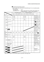
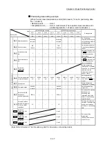
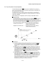
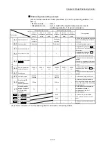
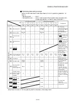
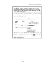
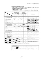
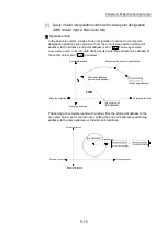
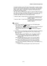
Positioning data setting example
[When "3-axis fixed-feed control (fixed-feed 3)" is set in positioning data No. 1 of
axis 1]
• Reference axis ............. Axis 1
• Interpolation axis.......... Axis 2, Axis3 (The required values are also set in
positioning data No. 1 of axis 2 and axis 3.)
Axis
Setting item
LD77MS4 setting example
LD77MS16 setting example
Setting details
Axis 1
(reference
axis)
Axis 2
(interpolation
axis)
Axis 3
(interpolation
axis)
Axis 1
(reference
axis)
Axis 2
(interpolation
axis)
Axis 3
(interpolation
axis)
A
xi
s 1
P
os
iti
on
in
g da
ta
No
. 1
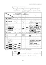
Da.1
Operation pattern
Positioning
complete
– –
Positioning
complete
– –
Set "Positioning complete" assuming
the next positioning data will not be
executed.
Da.2
Control method
Fixed-feed 3
–
–
Fixed-feed 3
–
–
Set 3-axis fixed-feed control.
Da.3
Acceleration
time
No.
1 – – 1 – –
Designate the value set in "
Pr.25
Acceleration time 1
" as the acceleration
time at start.
Da.4
Deceleration
time
No.
0 – – 0 – –
Designate the value set in "
Pr.10
Deceleration time 0
" as the
deceleration time at deceleration.
Da.5
Axis to be interpolated
LD77MS4
– – –
Setting not required (setting value is
ignored).
When axis 1 is used as a reference
axis, the interpolation axes are axes
2 and 3.
Da.6
Positioning address/
movement amount
10000.0
m
5000.0
m
6000.0
m
10000.0
m
5000.0
m
6000.0
m
Set the positioning address.
(Assuming "mm" is set in "
Pr.1
Unit
setting
".)
Da.7
Arc
address
– – – – – –
Setting not required (setting value is
ignored).
Da.8
Command speed
6000.00
mm/min
– –
6000.00
mm/min
– –
Set the speed during movement.
Da.9
Dwell time/JUMP
destination
positioning data No.
500ms –
– 500ms –
–
Set the time the machine dwells
after the positioning stop (command
stop) to the output of the positioning
complete signal.
Da.10
M code/Condition
data No./Number of
LOOP to LEND
repetitions
10 – – 10 – –
Set this when other sub operation
commands are issued in
combination with the No. 1
positioning data.
Da.20
Axis to be interpolated
No.1
LD77MS16
Axis 2
–
–
Set the axis to be interpolated.
If the self-axis is set, an error will
occur.
Da.21
Axis to be interpolated
No.2
LD77MS16
Axis
3
–
–
Da.22
Axis to be interpolated
No.3
LD77MS16
–
–
–
Setting not required (setting value is
ignored).
(Note): Refer to Section 5.3 "List of positioning data" for information on the setting details.
Содержание MELSEC-L Series
Страница 1: ...MELSEC L LD77MS Simple Motion Module User s Manual Positioning Control LD77MS2 LD77MS4 LD77MS16 ...
Страница 2: ......
Страница 30: ...MEMO ...
Страница 70: ...2 10 Chapter 2 System Configuration MEMO ...
Страница 83: ...3 13 Chapter 3 Specifications and Functions MEMO ...
Страница 103: ...3 33 Chapter 3 Specifications and Functions MEMO ...
Страница 107: ...3 37 Chapter 3 Specifications and Functions MEMO ...
Страница 111: ...3 41 Chapter 3 Specifications and Functions MEMO ...
Страница 115: ...3 45 Chapter 3 Specifications and Functions MEMO ...
Страница 140: ...4 22 Chapter 4 Installation Wiring and Maintenance of the Product MEMO ...
Страница 253: ...5 113 Chapter 5 Data Used for Positioning Control MEMO ...
Страница 342: ...5 202 Chapter 5 Data Used for Positioning Control MEMO ...
Страница 438: ...7 20 Chapter 7 Memory Configuration and Data Process MEMO ...
Страница 440: ...MEMO ...
Страница 485: ...9 25 Chapter 9 Major Positioning Control MEMO ...
Страница 594: ...9 134 Chapter 9 Major Positioning Control MEMO ...
Страница 624: ...10 30 Chapter 10 High Level Positioning Control MEMO ...
Страница 656: ...11 32 Chapter 11 Manual Control MEMO ...
Страница 690: ...12 34 Chapter 12 Expansion Control MEMO ...
Страница 798: ...13 108 Chapter 13 Control Sub Functions MEMO ...
Страница 866: ...14 68 Chapter 14 Common Functions MEMO ...
Страница 884: ...15 18 Chapter 15 Dedicated Instructions MEMO ...
Страница 899: ...16 15 Chapter 16 Troubleshooting MEMO ...
Страница 1036: ...Appendix 88 Appendices MEMO ...
Страница 1039: ......


