


4 - 20
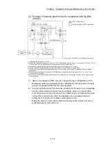
Chapter 4 Installation, Wiring and Maintenance of the Product
4.4 Confirming the installation and wiring
4.4.1 Items to confirm when installation and wiring are completed
Check the following points when completed with the installation of Simple Motion
module and wiring.
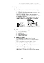
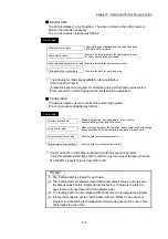
Is the module correctly wired?
The following four points are confirmed using the positioning test function of
GX Works2.
With this function, "whether the direction that the Simple Motion module recognizes as
forward run matches the address increment direction in the actual positioning work",
and "whether the Simple Motion module recognizes the external input signals such as
the manual pulse generator and forced stop", etc., can be checked.
Are the Simple Motion module and servo amplifier correctly connected?
Are the servo amplifier and servomotor correctly connected?
Are the Simple Motion module and external devices (input signals) correctly
connected?
Are the servo amplifier and external wiring (FLS, RLS, and DOG) correctly
connected?
Refer to the "Simple Motion Module Setting Tool Help" of GX Works2 for details of
"Positioning test function".
Note that the monitor data of the "
Md.30
External input signal" in the GX Works2 may
also be used to "confirm the connection between the Simple Motion module and
external devices (input signals)".
Important
If the Simple Motion module is faulty, or when the required signals such as the near-point dog signal
and forced stop signal are not recognized, unexpected accidents such as "not decelerating at the near-
point dog during machine OPR and colliding with the stopper", or "not being able to stop with the forced
stop signal" may occur. Execute a checking wiring of external input signal. The connection confirmation
by positioning test function must be carried out not only when structuring the positioning system, but
also when the system has been changed with module replacement or rewiring, etc.
Содержание MELSEC-L Series
Страница 1: ...MELSEC L LD77MS Simple Motion Module User s Manual Positioning Control LD77MS2 LD77MS4 LD77MS16 ...
Страница 2: ......
Страница 30: ...MEMO ...
Страница 70: ...2 10 Chapter 2 System Configuration MEMO ...
Страница 83: ...3 13 Chapter 3 Specifications and Functions MEMO ...
Страница 103: ...3 33 Chapter 3 Specifications and Functions MEMO ...
Страница 107: ...3 37 Chapter 3 Specifications and Functions MEMO ...
Страница 111: ...3 41 Chapter 3 Specifications and Functions MEMO ...
Страница 115: ...3 45 Chapter 3 Specifications and Functions MEMO ...
Страница 140: ...4 22 Chapter 4 Installation Wiring and Maintenance of the Product MEMO ...
Страница 253: ...5 113 Chapter 5 Data Used for Positioning Control MEMO ...
Страница 342: ...5 202 Chapter 5 Data Used for Positioning Control MEMO ...
Страница 438: ...7 20 Chapter 7 Memory Configuration and Data Process MEMO ...
Страница 440: ...MEMO ...
Страница 485: ...9 25 Chapter 9 Major Positioning Control MEMO ...
Страница 594: ...9 134 Chapter 9 Major Positioning Control MEMO ...
Страница 624: ...10 30 Chapter 10 High Level Positioning Control MEMO ...
Страница 656: ...11 32 Chapter 11 Manual Control MEMO ...
Страница 690: ...12 34 Chapter 12 Expansion Control MEMO ...
Страница 798: ...13 108 Chapter 13 Control Sub Functions MEMO ...
Страница 866: ...14 68 Chapter 14 Common Functions MEMO ...
Страница 884: ...15 18 Chapter 15 Dedicated Instructions MEMO ...
Страница 899: ...16 15 Chapter 16 Troubleshooting MEMO ...
Страница 1036: ...Appendix 88 Appendices MEMO ...
Страница 1039: ......


