


13 - 6
Chapter 13 Control Sub Functions
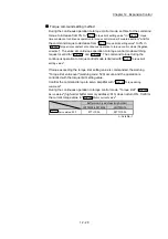
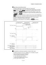
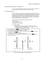
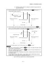
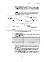
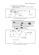
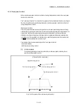
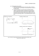
(3) Setting the dwell time during an OPR retry
The OPR retry function can perform such function as the dwell time using
"
Pr.57
Dwell time during OPR retry
" when the reverse run operation is carried
out due to detection by the limit signal for upper and lower limits and when
the machine OPR is executed after the near point dog is turned OFF to stop
the operation.
"
Pr.57
Dwell time during OPR retry
" is validated when the operation stops at
the "A" and "B" positions in the following drawing. (The dwell time is the
same value at both positions "A" and "B".)
Hardware limit switch
Limit signal OFF
Stop by limit
signal detection
A
OP
Machine OPR start
Reverse run operation
after limit signal detection
Stop by near-point
dog OFF
Near-point dog
Zero signal
Machine OPR
executed again
Pr. 44
B
OPR direction
Fig. 13.3 Setting the dwell time during an OPR retry
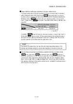
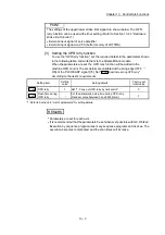
[2] Precaution during control
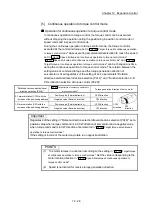
(1) The following table shows whether the OPR retry function may be executed
by the "
Pr.43
OPR method
".
Pr.43
OPR method
Execution status of OPR retry function
Near-point dog method
: Execution possible
Count method 1)
: Execution possible
Count method 2)
: Execution possible
Data set method
Scale origin signal detection method
: Execution not possible
Driver OPR method
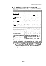
(2) Always establish upper/lower limit switches at the upper/lower limit positions
of the machine. If the OPR retry function is used without hardware stroke
limit switches, the motor will continue rotation until a hardware stroke limit
signal is detected.
(3) Do not configure a system so that the servo amplifier power turns OFF by
the upper/lower limit switches. If the servo amplifier power is turned OFF,
the OPR retry cannot be carried out.
(4) The operation decelerates upon detection of the hardware limit signal, and
the movement starts in the opposite direction. In this case, however, the
error "Hardware stroke limit (+)" (error code: 104) or "Hardware stroke limit
(–)" (error code: 105) does not occur.
Содержание MELSEC-L Series
Страница 1: ...MELSEC L LD77MS Simple Motion Module User s Manual Positioning Control LD77MS2 LD77MS4 LD77MS16 ...
Страница 2: ......
Страница 30: ...MEMO ...
Страница 70: ...2 10 Chapter 2 System Configuration MEMO ...
Страница 83: ...3 13 Chapter 3 Specifications and Functions MEMO ...
Страница 103: ...3 33 Chapter 3 Specifications and Functions MEMO ...
Страница 107: ...3 37 Chapter 3 Specifications and Functions MEMO ...
Страница 111: ...3 41 Chapter 3 Specifications and Functions MEMO ...
Страница 115: ...3 45 Chapter 3 Specifications and Functions MEMO ...
Страница 140: ...4 22 Chapter 4 Installation Wiring and Maintenance of the Product MEMO ...
Страница 253: ...5 113 Chapter 5 Data Used for Positioning Control MEMO ...
Страница 342: ...5 202 Chapter 5 Data Used for Positioning Control MEMO ...
Страница 438: ...7 20 Chapter 7 Memory Configuration and Data Process MEMO ...
Страница 440: ...MEMO ...
Страница 485: ...9 25 Chapter 9 Major Positioning Control MEMO ...
Страница 594: ...9 134 Chapter 9 Major Positioning Control MEMO ...
Страница 624: ...10 30 Chapter 10 High Level Positioning Control MEMO ...
Страница 656: ...11 32 Chapter 11 Manual Control MEMO ...
Страница 690: ...12 34 Chapter 12 Expansion Control MEMO ...
Страница 798: ...13 108 Chapter 13 Control Sub Functions MEMO ...
Страница 866: ...14 68 Chapter 14 Common Functions MEMO ...
Страница 884: ...15 18 Chapter 15 Dedicated Instructions MEMO ...
Страница 899: ...16 15 Chapter 16 Troubleshooting MEMO ...
Страница 1036: ...Appendix 88 Appendices MEMO ...
Страница 1039: ......


