
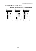


3 - 30
Chapter 3 Specifications and Functions
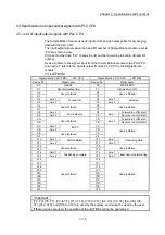
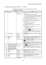
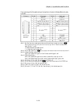
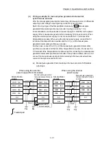
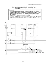
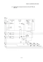
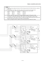
(3) Manual pulse generator/Incremental synchronous encoder input
(a) Interface between manual pulse generator/incremental synchronous
encoder (Differential-output type)
Input or
Output
Signal name
Pin No.
Wiring example Internal circuit
Input
Manual
pulse
generator,
phase A/
PLS
Power
supply
SG
Manual
pulse
generator,
phase B/
SIGN
4
5
17
18
1
14
2
15
Manual pulse
generator/
Incremental
synchronous
encoder
5V
SG
A
A
B
B
Power supply
5VDC
HAH
(A+)
HAL
(A-)
HBH
(B+)
HBL
(B-)
(Note-1),
(Note-2)
(Note-1): Set "0: Differential-output type" in " Manual pulse generator/Incremental synchronous encoder input type
selection" if the manual pulse generator/Incremental synchronous encoder of differential-output type is used.
The default value is "0: Differential-output type".
(Note-2): Set the signal input form in " Manual pulse generator/Incremental synchronous encoder input selection".
(Note-3): The 5VDC power supply from the Simple Motion module must not be used if a separate power supply is applied
to the manual pulse generator/incremental synchronous encoder.
If a separate power supply is used, use a stabilized power supply of voltage 5VDC.
Anything else may cause a failure.
Pr.24
Pr.89
5V
(Note-3)
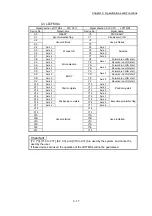
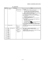
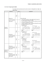
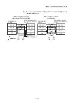
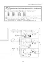
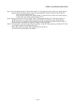
(b) Interface between manual pulse generator/Incremental synchronous
encoder (Voltage-output type/open-collector type)
(Note-1): Set "1: Voltage-output/open-collector type" in " Manual pulse generator/Incremental synchronous
encoder input type selection" if the manual pulse generator/Incremental synchronous encoder of voltage-
output/open-collector type is used.
The default value is "0: Differential-output type".
(Note-2): Set the signal input form in " Manual pulse generator/Incremental synchronous encoder input selection".
(Note-3): The 5VDC power supply from the Simple Motion module must not be used if a separate power supply is applied
to the manual pulse generator/Incremental synchronous encoder.
If a separate power supply is used, use a stabilized power supply of voltage 5VDC.
Anything else may cause a failure.
Pr.24
Pr.89
A
Manual pulse
generator/
Incremental
synchronous
encoder
5V
SG
B
Power supply
5VDC
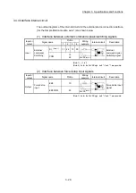
Input or
Output
Signal name
Pin No.
Wiring example Internal circuit
Power
supply
SG
3
16
1
14
2
15
Manual
pulse
generator,
phase A/
PLS
Manual
pulse
generator,
phase B/
SIGN
Input
(Note-1),
(Note-2)
5V
(Note-3)
HA
(A)
HB
(B)
Содержание MELSEC-L Series
Страница 1: ...MELSEC L LD77MS Simple Motion Module User s Manual Positioning Control LD77MS2 LD77MS4 LD77MS16 ...
Страница 2: ......
Страница 30: ...MEMO ...
Страница 70: ...2 10 Chapter 2 System Configuration MEMO ...
Страница 83: ...3 13 Chapter 3 Specifications and Functions MEMO ...
Страница 103: ...3 33 Chapter 3 Specifications and Functions MEMO ...
Страница 107: ...3 37 Chapter 3 Specifications and Functions MEMO ...
Страница 111: ...3 41 Chapter 3 Specifications and Functions MEMO ...
Страница 115: ...3 45 Chapter 3 Specifications and Functions MEMO ...
Страница 140: ...4 22 Chapter 4 Installation Wiring and Maintenance of the Product MEMO ...
Страница 253: ...5 113 Chapter 5 Data Used for Positioning Control MEMO ...
Страница 342: ...5 202 Chapter 5 Data Used for Positioning Control MEMO ...
Страница 438: ...7 20 Chapter 7 Memory Configuration and Data Process MEMO ...
Страница 440: ...MEMO ...
Страница 485: ...9 25 Chapter 9 Major Positioning Control MEMO ...
Страница 594: ...9 134 Chapter 9 Major Positioning Control MEMO ...
Страница 624: ...10 30 Chapter 10 High Level Positioning Control MEMO ...
Страница 656: ...11 32 Chapter 11 Manual Control MEMO ...
Страница 690: ...12 34 Chapter 12 Expansion Control MEMO ...
Страница 798: ...13 108 Chapter 13 Control Sub Functions MEMO ...
Страница 866: ...14 68 Chapter 14 Common Functions MEMO ...
Страница 884: ...15 18 Chapter 15 Dedicated Instructions MEMO ...
Страница 899: ...16 15 Chapter 16 Troubleshooting MEMO ...
Страница 1036: ...Appendix 88 Appendices MEMO ...
Страница 1039: ......


