


3 - 19
Chapter 3 Specifications and Functions
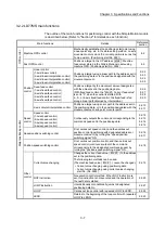
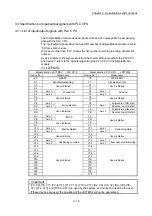
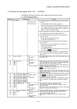
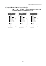
3.3.2 Details of input signals (LD77MS
PLC CPU)
The ON/OFF timing and conditions of the input signals are shown below.
(1) LD77MS2/LD77MS4
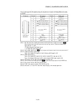
Device
No.
Signal name
Details
X0 READY
ON:
READY
OFF: Not READY/
Watch dog
timer error
• When the PLC READY signal [Y0] turns from OFF to ON, the parameter setting range
is checked. If no error is found, this signal turns ON.
• When the PLC READY signal [Y0] turns OFF, this signal turns OFF.
• When watch dog timer error occurs, this signal turns OFF.
• This signal is used for interlock in a sequence program, etc.
PLC READY signal [Y0]
OFF
ON
READY signal [X0]
OFF
ON
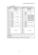
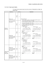
X1 Synchronization
flag
OFF:
Module
access
disabled
ON: Module
access
enabled
• After the PLC is turned ON or the CPU module is reset, this signal turns ON if the
access from the CPU module to the Simple Motion module is possible.
• When "Asynchronous" is selected in the module synchronization setting of the CPU
module, this signal can be used as interlock for the access from a sequence program
to the Simple Motion module.
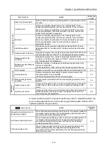
X4
X5
X6
X7
Axis 1
Axis 2
Axis 3
Axis 4
M code ON OFF: M code is
not set
ON: M code is
set
• In the WITH mode, this signal turns ON when the positioning data operation is started.
In the AFTER mode, this signal turns ON when the positioning data operation is
completed.
• This signal turns OFF with the "
Cd.7
M code OFF request
".
• When M code is not designated (when "
Da.10
M code/Condition data No./Number of
LOOP to LEND repetitions
" is "0"), this signal will remain OFF.
• With using continuous path control for the positioning operation, the positioning will
continue even when this signal does not turn OFF. However, a warning will occur.
(Warning code: 503)
• When the PLC READY signal [Y0] turns OFF, the M code ON signal will also turn
OFF.
• If operation is started while the M code is ON, an error will occur.
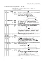
X8
X9
XA
XB
Axis 1
Axis 2
Axis 3
Axis 4
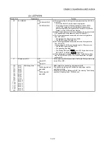
Error
detection
OFF: No error
ON: Error
occurrence
• This signal turns ON when an error listed in Section 16.4 occurs, and turns OFF when
the error is reset on "
Cd.5
Axis error reset".
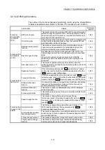
XC
XD
XE
XF
Axis 1
Axis 2
Axis 3
Axis 4
BUSY
(Note-1)
OFF: Not BUSY
ON: BUSY
• This signal turns ON at the start of positioning, OPR or JOG operation. It turns OFF
when the "
Da.9
Dwell time/JUMP destination positioning data No.
" has passed after
positioning stops. (This signal remains ON during positioning.)
• This signal turns OFF when the positioning is stopped with step operation.
• During manual pulse generator operation, this signal turns ON while the "
Cd.21
Manual pulse generator enable flag
" is ON.
• This signal turns OFF at error completion or positioning stop.
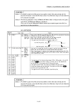
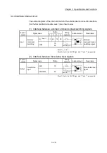
X10
X11
X12
X13
Axis 1
Axis 2
Axis 3
Axis 4
Start
complete
OFF: Start
incomplete
ON: Start
complete
• This signal turns ON when the positioning start signal turns ON and the Simple Motion
module starts the positioning process.
(The start complete signal also turns ON during OPR control.)
OFF
ON
OFF
ON
Positioning start signal [Y10]
Start complete signal [X10]
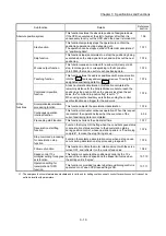
X14
X15
X16
X17
Axis 1
Axis 2
Axis 3
Axis 4
Positioning
complete
(Note-2)
OFF: Positioning
incomplete
ON: Positioning
complete
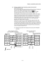
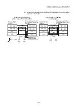
• This signal turns ON for the time set in "
Pr.40
Positioning complete signal output time
"
from the instant when the positioning control for each positioning data No. is
completed.
For the interpolation control, the positioning completed signal of interpolation axis
turns ON during the time set to the reference axis.
(It does not turn ON when "
Pr.40
Positioning complete signal output time
" is "0".)
• If positioning (including OPR), JOG/Inching operation, or manual pulse generator
operation is started while this signal is ON, the signal will turn OFF.
• This signal will not turn ON when speed control or positioning is canceled midway.
Содержание MELSEC-L Series
Страница 1: ...MELSEC L LD77MS Simple Motion Module User s Manual Positioning Control LD77MS2 LD77MS4 LD77MS16 ...
Страница 2: ......
Страница 30: ...MEMO ...
Страница 70: ...2 10 Chapter 2 System Configuration MEMO ...
Страница 83: ...3 13 Chapter 3 Specifications and Functions MEMO ...
Страница 103: ...3 33 Chapter 3 Specifications and Functions MEMO ...
Страница 107: ...3 37 Chapter 3 Specifications and Functions MEMO ...
Страница 111: ...3 41 Chapter 3 Specifications and Functions MEMO ...
Страница 115: ...3 45 Chapter 3 Specifications and Functions MEMO ...
Страница 140: ...4 22 Chapter 4 Installation Wiring and Maintenance of the Product MEMO ...
Страница 253: ...5 113 Chapter 5 Data Used for Positioning Control MEMO ...
Страница 342: ...5 202 Chapter 5 Data Used for Positioning Control MEMO ...
Страница 438: ...7 20 Chapter 7 Memory Configuration and Data Process MEMO ...
Страница 440: ...MEMO ...
Страница 485: ...9 25 Chapter 9 Major Positioning Control MEMO ...
Страница 594: ...9 134 Chapter 9 Major Positioning Control MEMO ...
Страница 624: ...10 30 Chapter 10 High Level Positioning Control MEMO ...
Страница 656: ...11 32 Chapter 11 Manual Control MEMO ...
Страница 690: ...12 34 Chapter 12 Expansion Control MEMO ...
Страница 798: ...13 108 Chapter 13 Control Sub Functions MEMO ...
Страница 866: ...14 68 Chapter 14 Common Functions MEMO ...
Страница 884: ...15 18 Chapter 15 Dedicated Instructions MEMO ...
Страница 899: ...16 15 Chapter 16 Troubleshooting MEMO ...
Страница 1036: ...Appendix 88 Appendices MEMO ...
Страница 1039: ......


