

5 - 32
Chapter 5 Data Used for Positioning Control
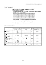
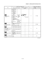
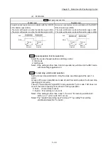
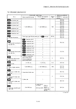
Pr.1
setting value
Value set with GX Works2
(unit)
Value set with sequence program
(unit)
0 : mm
0 to 6553.5 (
m)
0 to 65535 (
10
-1
m)
1 : inch
0 to 0.65535 (inch)
0 to 65535 (
10
-5
inch)
2 : degree
0 to 0.65535 (degree)
0 to 65535 (
10
-5
degree)
3 : PLS
0 to 65535 (PLS)
0 to 65535 (PLS)
0 to 32767
: Set as a decimal
32768 to 65535 : Convert into hexadecimal and set
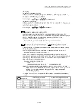
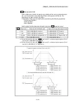
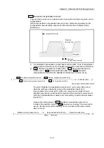
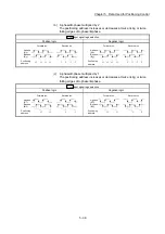
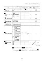
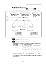
Pr.12
Software stroke limit upper limit value
Set the upper limit for the machine's movement range during positioning control.
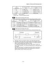
Pr.1
setting value
Value set with GX Works2
(unit)
Value set with sequence program
(unit)
0 : mm
-214748364.8 to 214748364.7 (
m)
-2147483648 to 2147483647 (
10
-1
m)
1 : inch
-21474.83648 to 21474.83647(inch) -2147483648 to 2147483647 (
10
-5
inch)
2 : degree
0 to 359.99999 (degree)
0 to 35999999 (
10
-5
degree)
3 : PLS
-2147483648 to 2147483647(PLS)
-2147483648 to 2147483647 (PLS)
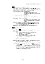
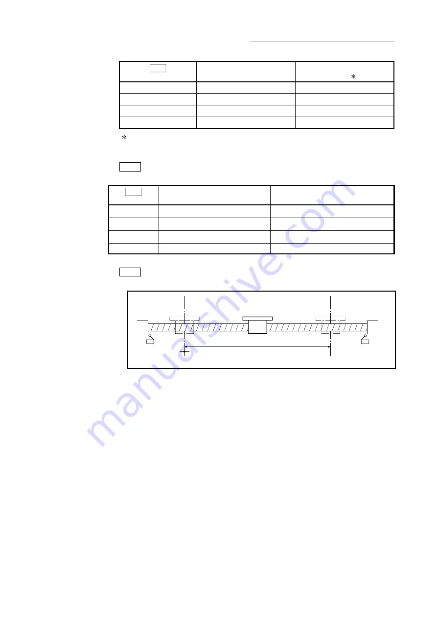
Pr.13
Software stroke limit lower limit value
Set the lower limit for the machine's movement range during positioning control.
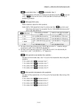
Software stroke
limit lower limit
Software stroke
limit upper limit
OP
(Machine movement range)
Emergency stop
limit switch
Emergency stop
limit switch
1) Generally, the OP is set at the lower limit or upper limit of the stroke limit.
2) By setting the upper limit value or lower limit value of the software stroke limit,
overrun can be prevented in the software. However, an emergency stop limit
switch must be installed nearby outside the range.
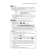
To invalidate the software stroke limit, set the setting value to "upper limit
value = lower limit value". (If it is within the setting range, the setting value can
be anything.)
When the unit is "degree", the software stroke limit check is invalid during
speed control (including the speed control in speed-position and position-
speed switching control) or during manual control.
Содержание MELSEC-L Series
Страница 1: ...MELSEC L LD77MS Simple Motion Module User s Manual Positioning Control LD77MS2 LD77MS4 LD77MS16 ...
Страница 2: ......
Страница 30: ...MEMO ...
Страница 70: ...2 10 Chapter 2 System Configuration MEMO ...
Страница 83: ...3 13 Chapter 3 Specifications and Functions MEMO ...
Страница 103: ...3 33 Chapter 3 Specifications and Functions MEMO ...
Страница 107: ...3 37 Chapter 3 Specifications and Functions MEMO ...
Страница 111: ...3 41 Chapter 3 Specifications and Functions MEMO ...
Страница 115: ...3 45 Chapter 3 Specifications and Functions MEMO ...
Страница 140: ...4 22 Chapter 4 Installation Wiring and Maintenance of the Product MEMO ...
Страница 253: ...5 113 Chapter 5 Data Used for Positioning Control MEMO ...
Страница 342: ...5 202 Chapter 5 Data Used for Positioning Control MEMO ...
Страница 438: ...7 20 Chapter 7 Memory Configuration and Data Process MEMO ...
Страница 440: ...MEMO ...
Страница 485: ...9 25 Chapter 9 Major Positioning Control MEMO ...
Страница 594: ...9 134 Chapter 9 Major Positioning Control MEMO ...
Страница 624: ...10 30 Chapter 10 High Level Positioning Control MEMO ...
Страница 656: ...11 32 Chapter 11 Manual Control MEMO ...
Страница 690: ...12 34 Chapter 12 Expansion Control MEMO ...
Страница 798: ...13 108 Chapter 13 Control Sub Functions MEMO ...
Страница 866: ...14 68 Chapter 14 Common Functions MEMO ...
Страница 884: ...15 18 Chapter 15 Dedicated Instructions MEMO ...
Страница 899: ...16 15 Chapter 16 Troubleshooting MEMO ...
Страница 1036: ...Appendix 88 Appendices MEMO ...
Страница 1039: ......


