


4 - 19
Chapter 4 Installation, Wiring and Maintenance of the Product
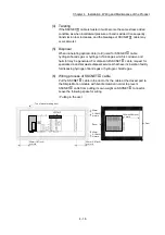
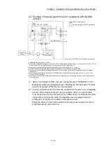
[4] Example of measure against noise for compliance with the EMC
directive.
PLC CPU LD77MS
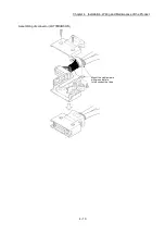
SSCNET cable
: AD75CK cable clamp
: Ferrite core (NEC TOKIN Corporation)
AC power
supply
NF
24VDC
power supply
Power
supply
4)
4)
2)
2)
2)
2)
1)
1)
7)
6)
5)
5)
7)
1)
3)
3)
1) Install a ferrite core. (Approx. 2 turn)
2) Ground the cables at a position 20 to 30cm (7.87 to 11.82inch) away from the module, or at a position 5 to 10cm (1.97 to
3.94inch) away from the exit/entrance of the control panel with the cable clamp, etc.
3) Wire the power supply cable as short as possible using the twisted cable (2mm
2
or more).
4) Use the shielded twisted cable (cable length: 30m (98.43ft.) or less) for each I/O signal cable.
5) Wire the cable connected to secondary side of 24VDC power supply module as short as possible using the shielded
twisted cable.
6) Wire the cable connected to FG terminal of LD77MS as short as possible using the cable of 0.517 to 1.31mm
2
, and
ground to the control panel.
7) Wire the power supply and 24VDC power supply as short as possible using the cable of approx. 2mm
2
, and ground to
the control panel.
Control panel: EC-SCF25-78 (Nitto Kogyo Corporation)
(1)
Refer to this chapter or "EMC and Low Voltage Directives" of "MELSEC-L CPU
Module User's Manual (Hardware Design, Maintenance and Inspection)" for basic
wire. We examined LD77MS by the above example.
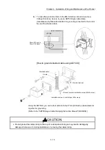
(2)
In wiring inside the panel, the power line connected to the power or servo amplifier
and the communication cable such as an expansion cable or a network cable
must not be mixed. In the duct, leave 10cm (3.94inch) or more between the power
line and the communication cable, and separate using a separator (made of
metal), etc. It is required in the same control panel as well.
Mixing the power line and communication cable may cause increase of noise or
malfunction due to noise influence.
Содержание MELSEC-L Series
Страница 1: ...MELSEC L LD77MS Simple Motion Module User s Manual Positioning Control LD77MS2 LD77MS4 LD77MS16 ...
Страница 2: ......
Страница 30: ...MEMO ...
Страница 70: ...2 10 Chapter 2 System Configuration MEMO ...
Страница 83: ...3 13 Chapter 3 Specifications and Functions MEMO ...
Страница 103: ...3 33 Chapter 3 Specifications and Functions MEMO ...
Страница 107: ...3 37 Chapter 3 Specifications and Functions MEMO ...
Страница 111: ...3 41 Chapter 3 Specifications and Functions MEMO ...
Страница 115: ...3 45 Chapter 3 Specifications and Functions MEMO ...
Страница 140: ...4 22 Chapter 4 Installation Wiring and Maintenance of the Product MEMO ...
Страница 253: ...5 113 Chapter 5 Data Used for Positioning Control MEMO ...
Страница 342: ...5 202 Chapter 5 Data Used for Positioning Control MEMO ...
Страница 438: ...7 20 Chapter 7 Memory Configuration and Data Process MEMO ...
Страница 440: ...MEMO ...
Страница 485: ...9 25 Chapter 9 Major Positioning Control MEMO ...
Страница 594: ...9 134 Chapter 9 Major Positioning Control MEMO ...
Страница 624: ...10 30 Chapter 10 High Level Positioning Control MEMO ...
Страница 656: ...11 32 Chapter 11 Manual Control MEMO ...
Страница 690: ...12 34 Chapter 12 Expansion Control MEMO ...
Страница 798: ...13 108 Chapter 13 Control Sub Functions MEMO ...
Страница 866: ...14 68 Chapter 14 Common Functions MEMO ...
Страница 884: ...15 18 Chapter 15 Dedicated Instructions MEMO ...
Страница 899: ...16 15 Chapter 16 Troubleshooting MEMO ...
Страница 1036: ...Appendix 88 Appendices MEMO ...
Страница 1039: ......


