

14 - 11
Chapter 14 Common Functions
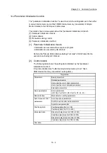
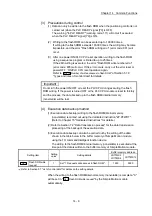
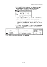
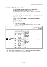
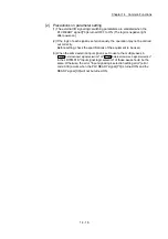
[2] Precautions during parameter setting
(1) When other than "1: External input signal of servo amplifier" and "2: Buffer
memory of LD77MS" is set, the error "External input signal selection error"
(error code: 936) occurs at turning when the PLC READY signal [Y0] ON, and
the READY signal [X0] is not turned ON.
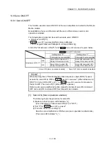
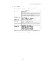
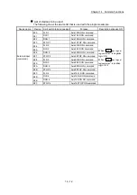
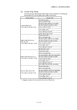
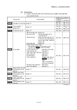
[3] Control details
The following table shows the external signal that becomes valid by setting
"
Pr.80
External input signal selection
".
"
Pr.80
External input signal selection"
External signal that becomes valid
External input signal of servo amplifier
(Setting value: 1)
Upper/lower stroke limit signal
: External input signal of servo amplifier
(FLS, RLS)
Near-point dog signal
: External input signal of servo amplifier
(DOG)
Stop signal
: Buffer memory of LD77MS (STOP)
External command/switching signal: External input signal of LD77MS (DI)
Buffer memory of LD77MS
(Setting value: 2)
Upper/lower stroke limit signal
: Buffer memory of LD77MS (FLS, RLS)
Near-point dog signal
: Buffer memory of LD77MS (DOG)
Stop signal
: Buffer memory of LD77MS (STOP)
External command/switching signal: External input signal of LD77MS (DI)
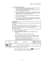
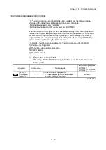
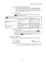
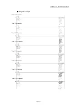
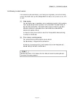
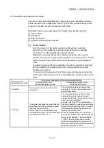
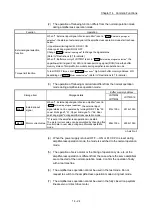
[4] Program example
The following shows the program example that is used to operate "
Cd.44
External input signal operation device
" of axis 1, axis 4, axis 8, and axis 16 using
the limit switch connected to the input module when "2: Buffer memory of
LD77MS" is set in "
Pr.80
External input signal selection
".
System configuration
The following shows the system configuration that is used with the program example.
FLS1
RLS1
DOG1
STOP1
FLS4
RLS4
DOG4
STOP4
(1)
(2)
(3) (4)
X20 to X5F
(1) L61P
(2) L26CPU
(3) LD77MS16 (X0 to X1F/Y0 to Y1F)
(4) LX42C4 (X20 to X5F)
Содержание MELSEC-L Series
Страница 1: ...MELSEC L LD77MS Simple Motion Module User s Manual Positioning Control LD77MS2 LD77MS4 LD77MS16 ...
Страница 2: ......
Страница 30: ...MEMO ...
Страница 70: ...2 10 Chapter 2 System Configuration MEMO ...
Страница 83: ...3 13 Chapter 3 Specifications and Functions MEMO ...
Страница 103: ...3 33 Chapter 3 Specifications and Functions MEMO ...
Страница 107: ...3 37 Chapter 3 Specifications and Functions MEMO ...
Страница 111: ...3 41 Chapter 3 Specifications and Functions MEMO ...
Страница 115: ...3 45 Chapter 3 Specifications and Functions MEMO ...
Страница 140: ...4 22 Chapter 4 Installation Wiring and Maintenance of the Product MEMO ...
Страница 253: ...5 113 Chapter 5 Data Used for Positioning Control MEMO ...
Страница 342: ...5 202 Chapter 5 Data Used for Positioning Control MEMO ...
Страница 438: ...7 20 Chapter 7 Memory Configuration and Data Process MEMO ...
Страница 440: ...MEMO ...
Страница 485: ...9 25 Chapter 9 Major Positioning Control MEMO ...
Страница 594: ...9 134 Chapter 9 Major Positioning Control MEMO ...
Страница 624: ...10 30 Chapter 10 High Level Positioning Control MEMO ...
Страница 656: ...11 32 Chapter 11 Manual Control MEMO ...
Страница 690: ...12 34 Chapter 12 Expansion Control MEMO ...
Страница 798: ...13 108 Chapter 13 Control Sub Functions MEMO ...
Страница 866: ...14 68 Chapter 14 Common Functions MEMO ...
Страница 884: ...15 18 Chapter 15 Dedicated Instructions MEMO ...
Страница 899: ...16 15 Chapter 16 Troubleshooting MEMO ...
Страница 1036: ...Appendix 88 Appendices MEMO ...
Страница 1039: ......


