


A - 7
(4) Wiring
CAUTION
Correctly and securely wire the wires. Reconfirm the connections for mistakes and the terminal
screws for tightness after wiring. Failing to do so may lead to run away of the servomotor.
After wiring, install the protective covers such as the terminal covers to the original positions.
Do not install a phase advancing capacitor, surge absorber or radio noise filter (option FR-BIF) on
the output side of the servo amplifier.
Correctly connect the output side (terminal U, V, W). Incorrect connections will lead the
servomotor to operate abnormally.
Do not connect a commercial power supply to the servomotor, as this may lead to trouble.
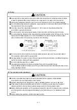
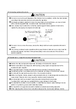
Do not mistake the direction of the surge absorbing diode installed on the DC relay for the control
signal output of brake signals, etc. Incorrect installation may lead to signals not being output
when trouble occurs or the protective functions not functioning.
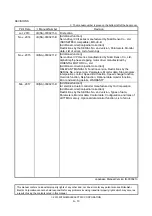
DICOM
RA
Control output
signal
DOCOM
Servo amplifier
24VDC
Control output
signal
DICOM
DOCOM
Servo amplifier
RA
24VDC
For the sink output interface
For the source output interface
Do not connect or disconnect the connection cables between each unit, the encoder cable or
PLC expansion cable while the power is ON.
Securely tighten the cable connector fixing screws and fixing mechanisms. Insufficient fixing may
lead to the cables combing off during operation.
Do not bundle the power line or cables.
Use applicable solderless terminals and tighten them with the specified torque.
If any solderless spade terminal is used, it may be disconnected when the terminal screw comes
loose, resulting in failure.
(5) Trial operation and adjustment
CAUTION
Confirm and adjust the program and each parameter before operation. Unpredictable
movements may occur depending on the machine.
Extreme adjustments and changes may lead to unstable operation, so never make them.
When using the absolute position system function, on starting up, and when the module or
absolute position motor has been replaced, always perform a home position return.
Before starting test operation, set the parameter speed limit value to the slowest value, and make
sure that operation can be stopped immediately by the forced stop, etc. if a hazardous state
occurs.
Before starting the operation, confirm the brake function.
Содержание MELSEC-L Series
Страница 1: ...MELSEC L LD77MS Simple Motion Module User s Manual Positioning Control LD77MS2 LD77MS4 LD77MS16 ...
Страница 2: ......
Страница 30: ...MEMO ...
Страница 70: ...2 10 Chapter 2 System Configuration MEMO ...
Страница 83: ...3 13 Chapter 3 Specifications and Functions MEMO ...
Страница 103: ...3 33 Chapter 3 Specifications and Functions MEMO ...
Страница 107: ...3 37 Chapter 3 Specifications and Functions MEMO ...
Страница 111: ...3 41 Chapter 3 Specifications and Functions MEMO ...
Страница 115: ...3 45 Chapter 3 Specifications and Functions MEMO ...
Страница 140: ...4 22 Chapter 4 Installation Wiring and Maintenance of the Product MEMO ...
Страница 253: ...5 113 Chapter 5 Data Used for Positioning Control MEMO ...
Страница 342: ...5 202 Chapter 5 Data Used for Positioning Control MEMO ...
Страница 438: ...7 20 Chapter 7 Memory Configuration and Data Process MEMO ...
Страница 440: ...MEMO ...
Страница 485: ...9 25 Chapter 9 Major Positioning Control MEMO ...
Страница 594: ...9 134 Chapter 9 Major Positioning Control MEMO ...
Страница 624: ...10 30 Chapter 10 High Level Positioning Control MEMO ...
Страница 656: ...11 32 Chapter 11 Manual Control MEMO ...
Страница 690: ...12 34 Chapter 12 Expansion Control MEMO ...
Страница 798: ...13 108 Chapter 13 Control Sub Functions MEMO ...
Страница 866: ...14 68 Chapter 14 Common Functions MEMO ...
Страница 884: ...15 18 Chapter 15 Dedicated Instructions MEMO ...
Страница 899: ...16 15 Chapter 16 Troubleshooting MEMO ...
Страница 1036: ...Appendix 88 Appendices MEMO ...
Страница 1039: ......


