


13 - 31
Chapter 13 Control Sub Functions
[4] Precautions during software stroke limit check
(1) A machine OPR must be executed beforehand for the "software stroke limit
function" to function properly.
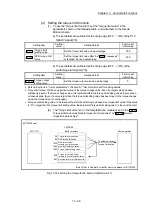
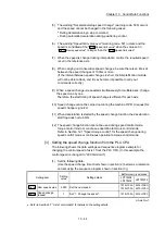
(2) During interpolation control, a stroke limit check is carried out for the every
current value of both the reference axis and the interpolation axis. Every
axis will not start if an error occurs, even if it only occurs in one axis.
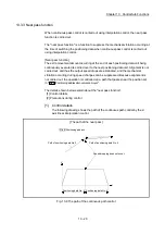
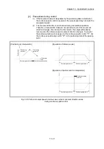
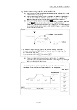
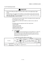
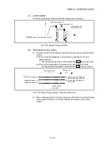
(3) During circular interpolation control, the "
Pr.12
Software stroke limit upper limit
value
"/"
Pr.13
Software stroke limit lower limit value
" may be exceeded.
In this case, a deceleration stop will not be carried out even if the stroke limit
is exceeded. Always install an external limit switch if there is a possibility the
stroke limit will be exceeded.
Arc address ( Da. 7 )
End point address ( Da. 6 )
Axis 1
Axis 1 stroke limit
Deceleration stop not carried out
Starting address
Axis 2
Example
: The software stroke limit check is carried out for the following addresses during circular
interpolation control. (Note that " Da. 7 Arc address" is carried out only for circular interpolation
control with sub point designation.)
Current value/end point address ( Da. 6 )/arc address ( Da. 7 )
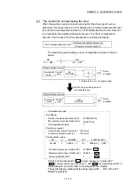
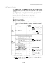
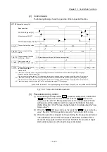
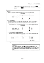
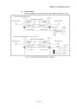
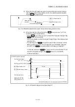
(4) If an error is detected during continuous path control, the axis stops
immediately on completion of execution of the positioning data located right
before the positioning data in error.
Md. 26
Axis operation status
No.10
No.11
No.12
No.13
Immediate stop at
error detection
No.10
P11
No.11
P11
No.12
P11
No.13
P11
No.14
P01
Position control
Error
Positioning data
• If the positioning address of positioning data No. 13 is outside the software stroke limit range,
the operation immediately stops after positioning data No. 12 has been executed.
Example
Содержание MELSEC-L Series
Страница 1: ...MELSEC L LD77MS Simple Motion Module User s Manual Positioning Control LD77MS2 LD77MS4 LD77MS16 ...
Страница 2: ......
Страница 30: ...MEMO ...
Страница 70: ...2 10 Chapter 2 System Configuration MEMO ...
Страница 83: ...3 13 Chapter 3 Specifications and Functions MEMO ...
Страница 103: ...3 33 Chapter 3 Specifications and Functions MEMO ...
Страница 107: ...3 37 Chapter 3 Specifications and Functions MEMO ...
Страница 111: ...3 41 Chapter 3 Specifications and Functions MEMO ...
Страница 115: ...3 45 Chapter 3 Specifications and Functions MEMO ...
Страница 140: ...4 22 Chapter 4 Installation Wiring and Maintenance of the Product MEMO ...
Страница 253: ...5 113 Chapter 5 Data Used for Positioning Control MEMO ...
Страница 342: ...5 202 Chapter 5 Data Used for Positioning Control MEMO ...
Страница 438: ...7 20 Chapter 7 Memory Configuration and Data Process MEMO ...
Страница 440: ...MEMO ...
Страница 485: ...9 25 Chapter 9 Major Positioning Control MEMO ...
Страница 594: ...9 134 Chapter 9 Major Positioning Control MEMO ...
Страница 624: ...10 30 Chapter 10 High Level Positioning Control MEMO ...
Страница 656: ...11 32 Chapter 11 Manual Control MEMO ...
Страница 690: ...12 34 Chapter 12 Expansion Control MEMO ...
Страница 798: ...13 108 Chapter 13 Control Sub Functions MEMO ...
Страница 866: ...14 68 Chapter 14 Common Functions MEMO ...
Страница 884: ...15 18 Chapter 15 Dedicated Instructions MEMO ...
Страница 899: ...16 15 Chapter 16 Troubleshooting MEMO ...
Страница 1036: ...Appendix 88 Appendices MEMO ...
Страница 1039: ......


