


13 - 49
Chapter 13 Control Sub Functions
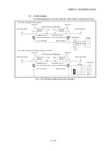
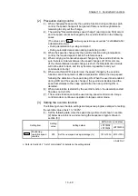
[2] Precaution during control
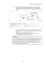
(1) When changing the speed by the override function during continuous path
control, the speed change will be ignored if there is not enough distance
remaining to carry out the change.
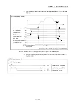
(2) The warning "Deceleration/stop speed change" (warning code: 500) occurs
and the speed cannot be changed by the override function in the following
cases.
(The value set in "
Cd.13
Positioning operation speed override
" is validated after
a deceleration stop.)
During deceleration by a stop command
During automatic deceleration during positioning control
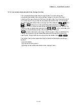
(3) When the speed is changed by the override function during interpolation
control, the required speed is set in the reference axis.
(4) When carrying out consecutive speed changes by the override function, be
sure there is an interval between the speed changes of 100ms or more.
(If the interval between speed changes is short, the Simple Motion module
will not be able to track, and it may become impossible to carry out
commands correctly.)
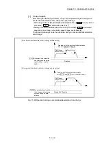
(5) When a machine OPR is performed, the speed change by the override
function cannot be carried out after a deceleration start to the creep speed
following the detection of near-point dog ON.
When the override is enabled
during OPR and the speed is changed, the override is disabled and the
speed accelerates to the creep speed after the near point dog ON is
detected.
(6) When deceleration is started by the override function, the deceleration start
flag does not turn ON.
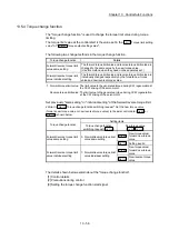
(7) The override function cannot be used during speed control mode, torque
control mode or continuous operation to torque control mode.
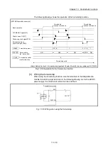
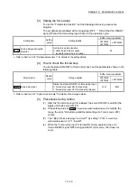
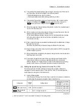
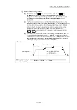
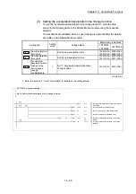
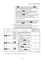
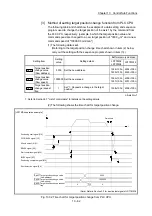
[3] Setting the override function
The following shows the data settings and sequence program example for setting
the override value of axis 1 to "200%".
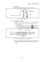
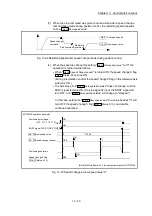
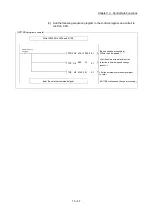
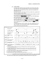
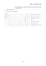
(1) Set the following data. (Use the speed change time chart shown in section
(2) below as a reference, and set using the sequence program shown in
section (3).)
Setting item
Setting
value
Setting details
Buffer memory address
LD77MS2
LD77MS4
LD77MS16
Cd.13
Positioning
operation speed
override
200
Set the new speed as a percentage (%).
1513+100n 4313+100n
n: Axis No.-1
: Refer to Section 5.7 "List of control data" for details on the setting details.
Содержание MELSEC-L Series
Страница 1: ...MELSEC L LD77MS Simple Motion Module User s Manual Positioning Control LD77MS2 LD77MS4 LD77MS16 ...
Страница 2: ......
Страница 30: ...MEMO ...
Страница 70: ...2 10 Chapter 2 System Configuration MEMO ...
Страница 83: ...3 13 Chapter 3 Specifications and Functions MEMO ...
Страница 103: ...3 33 Chapter 3 Specifications and Functions MEMO ...
Страница 107: ...3 37 Chapter 3 Specifications and Functions MEMO ...
Страница 111: ...3 41 Chapter 3 Specifications and Functions MEMO ...
Страница 115: ...3 45 Chapter 3 Specifications and Functions MEMO ...
Страница 140: ...4 22 Chapter 4 Installation Wiring and Maintenance of the Product MEMO ...
Страница 253: ...5 113 Chapter 5 Data Used for Positioning Control MEMO ...
Страница 342: ...5 202 Chapter 5 Data Used for Positioning Control MEMO ...
Страница 438: ...7 20 Chapter 7 Memory Configuration and Data Process MEMO ...
Страница 440: ...MEMO ...
Страница 485: ...9 25 Chapter 9 Major Positioning Control MEMO ...
Страница 594: ...9 134 Chapter 9 Major Positioning Control MEMO ...
Страница 624: ...10 30 Chapter 10 High Level Positioning Control MEMO ...
Страница 656: ...11 32 Chapter 11 Manual Control MEMO ...
Страница 690: ...12 34 Chapter 12 Expansion Control MEMO ...
Страница 798: ...13 108 Chapter 13 Control Sub Functions MEMO ...
Страница 866: ...14 68 Chapter 14 Common Functions MEMO ...
Страница 884: ...15 18 Chapter 15 Dedicated Instructions MEMO ...
Страница 899: ...16 15 Chapter 16 Troubleshooting MEMO ...
Страница 1036: ...Appendix 88 Appendices MEMO ...
Страница 1039: ......


