11 - 24
Chapter 11 Manual Control
11.4 Manual pulse generator operation
11.4.1 Outline of manual pulse generator operation
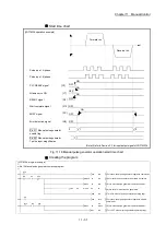
Manual pulse generator operation
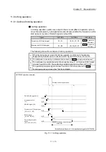
In manual pulse generator operations, pulses are input to the Simple Motion
module from the manual pulse generator. This causes the same number of input
command to be output from the Simple Motion module to the servo amplifier, and
the workpiece is moved in the designated direction.
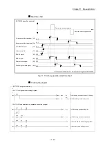
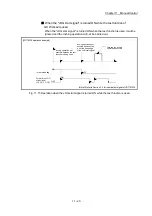
The following shows an example of manual pulse generator operation.
1)
When "
Cd.21
Manual pulse generator enable flag
" is set to "1", the BUSY signal turns ON and
the manual pulse generator operation is enabled.
2)
The workpiece is moved corresponding to the number of pulses input from the manual
pulse generator.
3)
The workpiece movement stops when no more pulses are input from the manual pulse
generator.
4)
When "
Cd.21
Manual pulse generator enable flag
" is set to "0", the BUSY signal turns OFF
and the manual pulse generator operation is disabled.
[LD77MS4 operation example]
Manual pulse
generator
operation stops
t
BUSY signal [XC, XD, YE, XF]
Manual pulse
generator input
Start complete signal
[X10, X11, X12, X13]
Manual pulse generator operation enabled
0
OFF
ON
OFF
1) 2)
3)
4)
1
0
Cd. 21 Manual pulse
generator enable flag
1
2
(Note): Refer to Section 3.3 for input/output signal of LD77MS16.
[Precautions]
1: If the input from the manual pulse generator stops, the machine will decelerate to a stop.
2: The start complete signal does not turn ON in manual pulse generator operation.
Fig. 11.16 Manual pulse generator operation
Important
Create the sequence program so that "
Cd.21
Manual pulse generator enable flag
" is
always set to "0" (disabled) when a manual pulse generator operation is not carried
out.
Mistakenly touching the manual pulse generator when the "manual pulse generator
enable flag" is set to "1" (enable) can cause accidents or incorrect positioning.
Содержание MELSEC-L Series
Страница 1: ...MELSEC L LD77MS Simple Motion Module User s Manual Positioning Control LD77MS2 LD77MS4 LD77MS16 ...
Страница 2: ......
Страница 30: ...MEMO ...
Страница 70: ...2 10 Chapter 2 System Configuration MEMO ...
Страница 83: ...3 13 Chapter 3 Specifications and Functions MEMO ...
Страница 103: ...3 33 Chapter 3 Specifications and Functions MEMO ...
Страница 107: ...3 37 Chapter 3 Specifications and Functions MEMO ...
Страница 111: ...3 41 Chapter 3 Specifications and Functions MEMO ...
Страница 115: ...3 45 Chapter 3 Specifications and Functions MEMO ...
Страница 140: ...4 22 Chapter 4 Installation Wiring and Maintenance of the Product MEMO ...
Страница 253: ...5 113 Chapter 5 Data Used for Positioning Control MEMO ...
Страница 342: ...5 202 Chapter 5 Data Used for Positioning Control MEMO ...
Страница 438: ...7 20 Chapter 7 Memory Configuration and Data Process MEMO ...
Страница 440: ...MEMO ...
Страница 485: ...9 25 Chapter 9 Major Positioning Control MEMO ...
Страница 594: ...9 134 Chapter 9 Major Positioning Control MEMO ...
Страница 624: ...10 30 Chapter 10 High Level Positioning Control MEMO ...
Страница 656: ...11 32 Chapter 11 Manual Control MEMO ...
Страница 690: ...12 34 Chapter 12 Expansion Control MEMO ...
Страница 798: ...13 108 Chapter 13 Control Sub Functions MEMO ...
Страница 866: ...14 68 Chapter 14 Common Functions MEMO ...
Страница 884: ...15 18 Chapter 15 Dedicated Instructions MEMO ...
Страница 899: ...16 15 Chapter 16 Troubleshooting MEMO ...
Страница 1036: ...Appendix 88 Appendices MEMO ...
Страница 1039: ......

