


11 - 10
Chapter 11 Manual Control
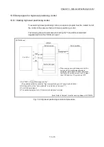
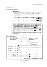
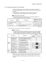
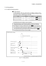
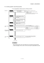
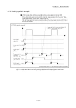
11.2.4 Creating start programs for JOG operation
A sequence program must be created to execute a JOG operation. Consider the
"required control data setting", "start conditions" and "start time chart" when creating
the program.
The following shows an example when a JOG operation is started for axis 1.
("
Cd.17
JOG speed" is set to "100.00mm/min" in the example shown.)
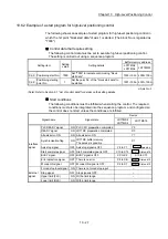
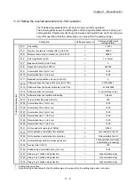
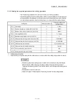
Required control data setting
The control data shown below must be set to execute a JOG operation. The
setting is carried out with the sequence program.
Setting item
Setting
value
Setting details
Buffer memory address
LD77MS2
LD77MS4
LD77MS16
Cd.16
Inching movement
amount
0 Set
"0".
1517+100n
4317+100n
Cd.17
JOG speed
10000 Set a value equal to or below the "
Pr.31
JOG speed limit value".
1518+100n
1519+100n
4318+100n
4319+100n
n: Axis No.-1
: Refer to Section 5.7 "List of control data" for details on the setting details.
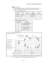
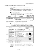
Start conditions
The following conditions must be fulfilled when starting. The required conditions
must also be assembled in the sequence program, and the sequence program
must be configured so the operation will not start if the conditions are not fulfilled.
Signal name
Signal state
Device
LD77MS2
LD77MS4
LD77MS16
Interface
signal
PLC READY signal
ON PLC CPU preparation completed
Y0
READY signal
ON LD77MS preparation completed
X0
All axis servo ON
ON All axis servo ON
Y1
Synchronization flag ON
LD77MS buffer memory
The access is possible.
X1
Axis stop signal
OFF Axis stop signal is OFF
Y4 to Y7
Cd.180
Axis stop
Start complete signal
OFF Start complete signal is OFF
X10 to X13
Md.31
Status: b14
BUSY signal
OFF LD77MS is not operating
XC to XF
X10 to X1F
Error detection signal
OFF There is no error
X8 to XB
Md.31
Status: b13
M code ON signal
OFF M code ON signal is OFF
X4 to X7
Md.31
Status: b12
External
signal
Forced stop input signal ON There is no forced stop input
–
Stop signal
OFF Stop signal is OFF
–
Upper limit (FLS)
ON Within limit range
–
Lower limit (RLS)
ON Within limit range
–
: If the PLC CPU is set to the asynchronous mode in the synchronization setting, this must be
inserted in the program for interlocking. If it is set to the synchronous mode, it must not be
inserted in the program for interlocking because it is turned ON when the PLC CPU executes
calculation.
Содержание MELSEC-L Series
Страница 1: ...MELSEC L LD77MS Simple Motion Module User s Manual Positioning Control LD77MS2 LD77MS4 LD77MS16 ...
Страница 2: ......
Страница 30: ...MEMO ...
Страница 70: ...2 10 Chapter 2 System Configuration MEMO ...
Страница 83: ...3 13 Chapter 3 Specifications and Functions MEMO ...
Страница 103: ...3 33 Chapter 3 Specifications and Functions MEMO ...
Страница 107: ...3 37 Chapter 3 Specifications and Functions MEMO ...
Страница 111: ...3 41 Chapter 3 Specifications and Functions MEMO ...
Страница 115: ...3 45 Chapter 3 Specifications and Functions MEMO ...
Страница 140: ...4 22 Chapter 4 Installation Wiring and Maintenance of the Product MEMO ...
Страница 253: ...5 113 Chapter 5 Data Used for Positioning Control MEMO ...
Страница 342: ...5 202 Chapter 5 Data Used for Positioning Control MEMO ...
Страница 438: ...7 20 Chapter 7 Memory Configuration and Data Process MEMO ...
Страница 440: ...MEMO ...
Страница 485: ...9 25 Chapter 9 Major Positioning Control MEMO ...
Страница 594: ...9 134 Chapter 9 Major Positioning Control MEMO ...
Страница 624: ...10 30 Chapter 10 High Level Positioning Control MEMO ...
Страница 656: ...11 32 Chapter 11 Manual Control MEMO ...
Страница 690: ...12 34 Chapter 12 Expansion Control MEMO ...
Страница 798: ...13 108 Chapter 13 Control Sub Functions MEMO ...
Страница 866: ...14 68 Chapter 14 Common Functions MEMO ...
Страница 884: ...15 18 Chapter 15 Dedicated Instructions MEMO ...
Страница 899: ...16 15 Chapter 16 Troubleshooting MEMO ...
Страница 1036: ...Appendix 88 Appendices MEMO ...
Страница 1039: ......


