HS Luma
HS Chroma
VS Ver Luma
VS Ver Chroma
VS Top Luma
VS Top Chroma
VS Bottom Luma
VS Bottom Chroma
192*4
224*4
255*4+3
HS Luma
HS Chroma
VS Ver Luma
VS Ver Chroma
(a) sc_h
(b) sc_m
0*4
32*4
64*4
96*4
128*4
160*4
191*4+3
31*4+3
63*4+3
95*4+3
127*4+3
159*4+3
223*4+3
31 0
31
0
0*4
32*4
64*4
96*4
31*4+3
63*4+3
95*4+3
127*4+3
Address
Address
Internal Modules
204
SPRUHI7A – December 2012 – Revised June 2016
Copyright © 2012–2016, Texas Instruments Incorporated
High-Definition Video Processing Subsystem (HDVPSS)
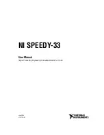
The module supports the VPI Control Read to read back the contents in the coefficient memories for
debug purpose.
shows the memory map of the VPI Control Read. As the VPI Control Read
has only 32 bit data bus, it requires the word addressing while the write does the quad-word addressing.
The VS top and bottom coefficients can be accessed separately for the read.
Figure 1-156. VPI Control I/F Memory Map (Read)
1.2.11.2.5.5 VPI Control Interface
VPDMA is used to configure the coefficient memories of scaler through VPI control interface. Since the
coefficient memories are not shadowed (unlike the MMR registers), VPI control write access needs to be
done only during the gap between video frame processing times. If a write request is made while the
Scaler is active, the access will be held off by the hardware until the last data of the currently processed
frame is sent out. Care must be given to the order of the DMA descriptors so that blocking of VPI control
bus does not occur.