MM4006
M
o
t
i
o
n
Control Tutorial
An origin switch (Fig. 4.22) separates the entire travel in two areas: one for
which it has a high level and one for which it is low. The most important
part of it is the transition between the two areas. Also, looking at the origin
switch level, the controller knows on which side of the transition it current-
ly is and which way to move to find it.
The task of the home search routine is to identify one unique index pulse
as the absolute position reference. This is clone by first finding the origin
switch transition and then the very first index pulse (Fig. 4.23).
Motion
Origin Switch
Encoder Index
Pulse
Fig. 4.23 — Slow-Speed Origin Switch Search.
So far, we can label the two motion segments D and E. During D the con-
troller is looking for the origin switch transition and during E for the index
pulse. To guarantee the best accuracy possible, both D and E segments are
performed at a very low speed and without a stop in-between. Also, during
E the display update is suppressed to eliminate any unnecessary overhead.
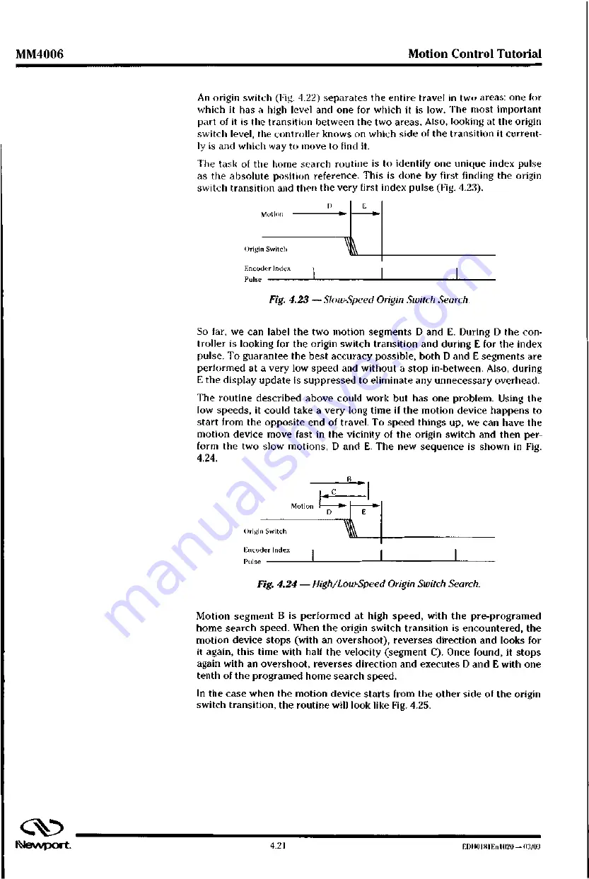
The routine described above could work but has one problem. Using the
low speeds, it could take a very long time if the motion device happens to
start from the opposite end of travel. To speed things up, we can have the
motion device move fast in the vicinity of the origin switch and then per-
form the two slow motions, D and E. The new sequence is shown in Fig.
4.24.
13
. 1 c
Motion
1 0 ,
Origin Switch
Encoder Index
Pulse
Fig. 4.24 — High/Low-Speed Origin Switch Search.
Motion segment B is performed at high speed, with the pre-programed
home search speed. When the origin switch transition is encountered, the
motion device stops (with an overshoot), reverses direction and looks for
it again, this time with half the velocity (segment C). Once found, it stops
again with an overshoot, reverses direction and executes D and E with one
tenth of the programed home search speed.
In the case when the motion device starts from the other side of the origin
switch transition, the routine will look like Fig. 4.25.
c v
N e v v p o r t
4
.
2
1
E r m i o l t t l E n 1 0 2 0 — (13/03
Summary of Contents for MM4006
Page 9: ...F D110181En1020 03 03 b J e w p o r t...
Page 11: ...MM4006 8 Axis Motion Controller Driver evvport...
Page 41: ...MM4006 Introduction FPI 111181Eli11120 0 1 03 1 3O tNevvport...
Page 42: ...Section 2 Local Mode C Newport...
Page 43: ...MM4006 8 Axis Motion Controller Driver C N e w p o r t...
Page 96: ...Section 3 Remote Mode C klevvport...
Page 97: ...Newport...
Page 310: ...Section 4 Motion Control Tutorial Ilevvport...
Page 311: ...MM4006 8 Axis Motion Controller Driver C EDI10181En 1020 03 03 2 N e V V p O r t...
Page 313: ...MM4006 8 Axis Motion Controller Driver cv ED110181E01020 03 03 4 2 M e v v p o r t...
Page 334: ...Section 5 Trajectory Functions Tutorial Newport...
Page 335: ...MM4006 8 Axis Motion Controller Driver C Newport...
Page 337: ...MM4006 8 Axis Motion Controller Driver EDH0181En1020 03 03 5 2 N e w p o r t...
Page 346: ...Section 6 Feature Descriptions Tutorial Newport...
Page 347: ...MM4006 8 Axis Motion Controller Driver C Nevvport...
Page 349: ...MM4006 8 Axis Motion Controller Driver ED11018lEn I 020 03 03 6 2 N e v v p O r t...
Page 359: ...MM4006 F e a t u r e Descriptions Tutorial cv EDI10181En1020 03 03 6 12 N e w p o r t...
Page 360: ...Section 7 Servo Tuning rano at 1 2 2 p EOF 110 1 0 0 0 0 0 ill fpL4 cv Newport...
Page 361: ...MM4006 8 Axis Motion Controller Driver C Nevvport...
Page 363: ...MM4006 8 Axis Motion Controller Driver EDH0181En 1020 03 03 7 2...
Page 368: ...Section 8 Appendices INevvport...
Page 369: ...MM4006 8 Axis Motion Controller Driver CkJ Newport...
Page 371: ...MM4006 8 Axis Motion Controller Driver EDI10181EnI020 03 03 8 2 N e v v p o r t...
Page 410: ...A7 h7s z c 7...


