MUTOH Falcon RJ-4100 Maintenance Manual Download Page 10

10

C O N 4 0 1 0

Model Name:

RJ–4100

C O N 4 0 1 0

Model Name:

RJ–4100

How to use the Maintenance Manual

How to use the Maintenance Manual

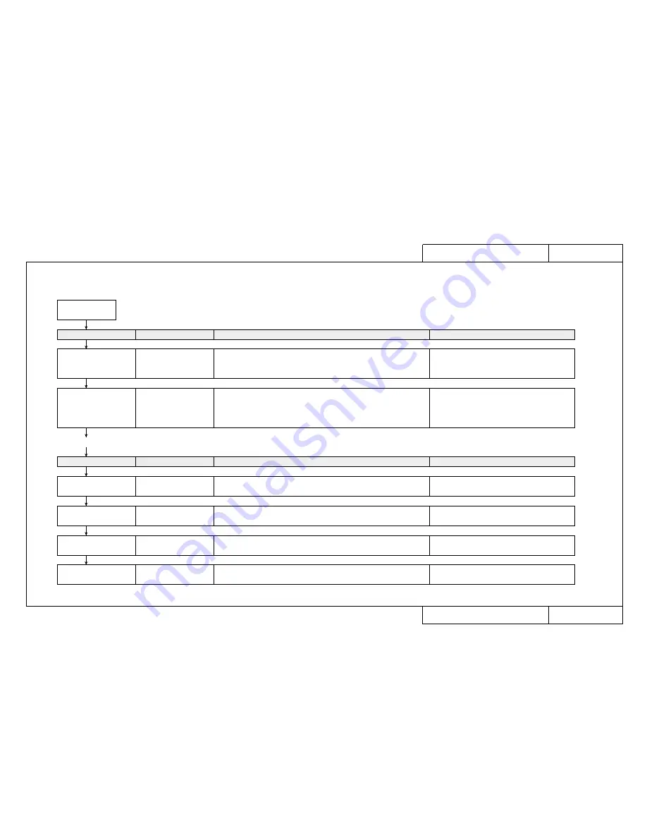
Fault maintenance work procedures and how to use the Maintenance Manual
When a user reports an equipment fault, use the following procedure to carry out fault recovery tasks.

A fault occurs

Task

Page

Details

Reference materials

Check fault circumstances, 
select fault details from 
Trouble-Shooting Lists

Trouble-Shooting List 
TRB

❉❉❉❉

Check circumstances by “fax” or “telephone”.  Check error 
messages, check user usage conditions, retry after changing settings, output 
diagnostic pattern, etc.  Select fault symptoms produced by user from 
the Trouble-Shooting List.

Conduct a consultation by “fax” or “telephone”.  
Check possibility of user error or recovery by daily inspection.  Check error 
messages, check user usage conditions, output diagnostic pattern, output 
setup list.  Retry after changing settings, etc.

Primary Consultation 
ENT

❉❉❉❉

Operation Manual, basic 
knowledge, daily care, periodic maintenance/
inspection/cleaning

Task

Page

Details

Reference materials

Gather the necessary 
maintenance parts

Matrix Map 
MAP

❉❉❉❉

Gather the necessary maintenance parts

Maintenance Parts list, Maintenance Tools list, 
Exploded views

Conduct a tracing inquiry

Fault Tracing Procedures 
EXA

❉❉❉❉

Conduct an inquiry to trace the cause of the fault

Basic knowledge

Replace parts and adjust

Replacement and Adjustment 
Procedures REP

❉❉❉❉

Replace or readjust parts suspected to be faulty.  
Carry out adjustments after replacing parts.

Basic knowledge

Final check

Test Procedures 
TST

❉❉❉❉

Separate causes of faults and check operation after faults have been 
rectified.

Conduct a primary 
consultation with the user

• If you are unable to resolve the fault at this point, take the necessary maintenance parts and make an on-site visit.

Summary of Contents for Falcon RJ-4100

Page 1: ...1 Full Color Inkjet Printer RJ 4100 RJ41 A 01 MAINTENANCE MANUAL ...

Page 2: ... Data Computer Company Windows 3 1 Windows 95 Windows NT 3 51 Windows NT 4 0 MS DOS are trademarks or trade names of the Microsoft Corporation Other names of products and companies are the trademarks or trade names of each relevant company This manual contains basic technical details necessary for marketplace servicing to maintain product quality and performance of RJ 4100 printer RJ 4100 printer ...

Page 3: ... with changed settings output test patterns etc 3 2 If it is not solved by the primary consultation take the necessary maintenance items and make an on site visit Assemble the necessary maintenance parts from the matrix map At the user s premises first check the symptoms Proceed with maintenance work in accordance with the fault tracing procedure After the repair work is finished be sure to check ...

Page 4: ...tall a new waste fluid box and clear the waste fluid counter 1 After head cleaning and initial filling 2 When it was not possible to capture main board backup parameters PRECAUTION 6 Take Care When Inserting Head Cable and Y Cable PRECAUTION 7 Ink and Cleaning Fluid Conduct Electricity When the print head assembly head board assembly and main board assembly have been replaced be careful to insert ...

Page 5: ...tion ENT2000 Trouble with Media Feed ENT3000 Trouble with Printing ENT4000 Problem Involving Noise ENT5000 Trouble with Media Cutting ENT6000 Online Function Problems ENT7000 Other ENT8000 Matrix Map MAP0000 When Message is Displayed Printer Status Messages MAP1000 Data Errors MAP1200 Command Errors MAP1250 CPU System Faults MAP1500 Mechanical System Faults MAP1700 When Message is not Displayed Tr...

Page 6: ...ame Assembly REP 1330 Ink ID Sensor Assembly Black Yellow Magenta Cyan REP 1340 Detector Assembly Black Yellow Magenta Cyan REP 1350 Y Cable A0 REP 1360 Ink Tubes A0 REP 1370 Cutter Solenoid Assembly REP 1380 Print Head Assembly Black REP 1390 Print Head Assembly Color REP 1400 Head Cable Black REP 1390 Head Cable Color REP 1400 Y Paper Sensor Assembly REP 1410 Head Board Assembly REP 1420 Dampers...

Page 7: ...al Standby Sequence GID4040 Encoder Disconnected Check Sequence GID4050 Origin Detection Sequence GID4060 Media Cutting Sequence GID4070 Monochrome Printing Sequence Including Flushing GID4080 Color Printing Sequence Including Flushing GID4090 Stored Test Patterns PAT0000 Presentation Pattern PAT1000 Color palette PAT2000 Print quality adjustment pattern PAT3000 Setup List PAT4000 Self Diagnosis F...

Page 8: ...ion BAC4000 Adjustment Parameters BAC4000 Parameters BAC5000 Initialize BAC5010 Update BAC5020 Aging BAC6000 Carriage Motor BAC6010 Media Feed Motor BAC6020 Cutter BAC6030 Maintenance Unit BAC6040 Head BAC6050 Maintenance Parts CAT0000 Maintenance Parts List CAT1000 Maintenance Tool List CAT2000 Adhesives and Tapes CAT3000 Lubrication Points CAT4000 Exploded View Drawing CAT5000 8 ...

Page 9: ...e the Maintenance Manual How to use the Maintenance Manual CON4010 How to use the Trouble Shooting Lists TRB CON4020 How to use Primary Consultation ENT CON4030 How to use the Matrix Map MAP CON4040 How to use the Fault Tracing Procedure EXA CON4050 How to use Replacement and Adjustment Procedure REP CON4060 How to use Test Procedure TST CON4070 ...

Page 10: ...ck error messages check user usage conditions output diagnostic pattern output setup list Retry after changing settings etc Primary Consultation ENT Operation Manual basic knowledge daily care periodic maintenance inspection cleaning Task Page Details Reference materials Gather the necessary maintenance parts Matrix Map MAP Gather the necessary maintenance parts Maintenance Parts list Maintenance ...

Page 11: ... Printer Status Messages Data Errors Command Errors CPU System Faults Mechanical System Faults When Message is Not Displayed TRB2000 to TRB2001 Trouble with Initialization Troubles that occur when unpacking immediately after delivery are grouped here Check this group for a similar trouble occurring other than immediately after delivery Troubles concerning the series of operations up to the enablin...

Page 12: ...ure it is connected to a 100 V or 200 V ground and confirm by testing the display again With the cord inserted into the power outlet is the prescribed voltage available at the end of the cord Switch off the printer leave it for ten minutes then try switching on again The overcurrent detector circuit in the printer s power supply may have tripped Leave it for 10 minutes then try switching on again ...

Page 13: ...cartridges are installed but not recognized Can not make entries from the operating panel Data is received but not plotted Media is not suction Replacement and Adjustment Procedure REP No Name and Diagram Number of Replacement Part DF 41524 Main Board Assembly DF 40097 Panel Board Assembly DF 40114 Panel Cable DF 40100 Cover Switch Assembly DF 40099 Lever Sensor Assembly DF 40108 Paper Sensor Y As...

Page 14: ...ble assembly between the switch and power supply board Use a tester to check for broken or shorted leads Replace the switch cable assembly Do the Power supply voltage check 100 V AC Do the Power supply voltage check 5 V DC Do the Power supply voltage check 24 42 V DC Check the panel cable connectors on the panel board and main board Are they inserted obliquely Are they securely locked Check Main b...

Page 15: ... TO TEST NO 1001 TEST4 Item Replacement and Adjustment Procedure 1 Replacement Procedure 2 Adjustment and Examination Procedure Replace the Y Motor Assembly 1 Remove the Left and Right Covers Refer to REP1010 2 Remove the Rear Paper Guide Refer to REP1040 3 Remove the Steel Belt Refer to REP1290 4 Open the Control Box Refer to REP1050 5 Disconnect connector J119 YMOT from the Main Board Assembly 6...

Page 16: ...ad A3 size media in the printer 2 Print a Test Print Press the Resolution key while you hold down the Shift key 3 Check that the printing is normal Refer to PAT1000 for checking printing quality 1 Load roll media in the printer thick coated paper 2 Select Adjustments Skew Verification from the self diagnostics menu Refer to BAC2030 3 When Please input paper feed length m default 1 0 m is displayed...

Page 17: ...on explains the details of daily maintenance including cleaning ink cartridge replacement cutter replacement etc How to Clean the Printer Main Unit CON5010 How to Clean the Printer Main Unit CON5011 How to Replace Ink Cartridges CON5020 How to Replace the Cutter CON5030 How to Replace the Waste Fluid Box CON5040 ...

Page 18: ...g cleaning Paper dust which is produced when the printer is working should be removed periodically Make sure that it does not get blown around Stubborn dirt that is difficult to remove may be removed with a lint free cloth dampened with alcohol CAUTION Paper dust and fluff will accumulate with long term use and stick to the plotting board and cutter groove and may cause printing quality and cuttin...

Page 19: ...n Unit Use a cotton bud to wipe away any dust and paper fluff from the front and back paper sensor covers in two places Paper Sensor Cover Progressive soiling will affect the sensitivity of the sensors and faulty detection of the media in the initial operation may cause a Skew Check Error They must be cleaned periodically IMPORTANT ...

Page 20: ...00 C O N 5 0 2 0 Model Name RJ 4100 How to Replace Ink Cartridges How to Replace Ink Cartridges Step 3 Insert the new cartridge in the slot at the back of the printer Step 4 Check that the display has reverted to its permanent display Reference Only specific cartridges can be used They also have a particular place and orientation Be careful not to confuse the location and orientation Don t open th...

Page 21: ...ead As you push down on the cutter restore the cut ter arm over the cutter The cutter will only go in one way Cutter Arm There is a spring in the cutter mounting hole Be careful not to lose it when you replace the cutter CAUTION The cutter blade is very hard and brittle Be careful not to knock it or drop it Step 4 Return the head to the right end and switch on the power CAUTION Since the life of t...

Page 22: ...te Ink Tank Step 4 Insert a new waste fluid box in the printer Step 5 Use the VALUE or VALUE keys on the purple part of the operating panel to change the display to Yes Step 6 Press the Enter key on the purple part of the operating panel The waste fluid box can be treated as non combustible garbage Don t squeeze the absorbent sheet soaked with waste fluid or the waste fluid may leak Since it would...

Page 23: ...ning jig Packing tape gum tape bubble wrap PP strapping and stopper for long distance transportation CAUTION For safety always have two people to dismantle and assemble the printer Always have two people to transport the printer and load and unload it on the vehicle If the user wishes you to take away the waste fluid box that has been removed and the packing used for transportation remove them Aft...

Page 24: ...01 and Mechanical System Faults Printer Status Messages TRB1000 Data Errors TRB1000 Command Errors TRB1000 CPU System Faults TRB1000 Mechanical System Faults TRB1000 When Message is Not Displayed Trouble with Initialization TRB2000 Trouble with Printing TRB2000 Trouble with Media Feed TRB2000 Trouble with Media Cutting TRB2001 Problem Involving Noise TRB2001 Online Function Problems TRB2001 Other ...

Page 25: ... E 0 1 6 C P U E r r 0 6 Bus error exception Command fetch E 0 1 6 C P U E r r 0 7 Bus error exception Data load E 0 1 6 C P U E r r 0 8 System call exception error E 0 1 6 C P U E r r 0 9 Break point exception error E 0 1 6 C P U E r r 1 0 Reserved command exception error E 0 1 6 C P U E r r 1 1 Unable to use coprocessor exception error E 0 1 6 C P U E r r 1 2 Operation overflow exception error E...

Page 26: ...r r 3 3 E237 Error Transfer memory E129 Error NVRAM Standard DRAM error Optional DRAM 1 error Optional DRAM 2 error Interrupt exception error Command boundary exception error Data boundary exception error Address error exception Load or command fetch Address error exception Store Bus error exception Command fetch Bus error exception Data load System call exception error Break point exception error...

Page 27: ...shed Dots are missing from the printing Cleaning does not cure blockage Does not print at all Does not print a specific color The entire surface is printed black Printing becomes shaded The image contains blurs Transverse lines appear to be split Black and white lines appear in the printed image Edges of printing are blurred Many satellites unwanted dots The printing has whiskers Printed lines app...

Page 28: ...verflowed from the waste fluid box Ink overflows from flushing box Ink is split around the X rail Trouble related to ink consumable item Trouble related to media consumable item Trouble related to cutters consumable item Trouble related to extended memory optional item Trouble related to the network board optional item Can not install the printer driver Cannot connect normally with Centronics Cann...

Page 29: ...Status Messages ENT1000 Data Errors ENT1200 Command Errors ENT1250 CPU System Faults ENT1500 Mechanical System Faults ENT1700 When Message is Not Displayed Trouble with Initialization ENT2000 Trouble with Printing ENT4000 Trouble with Media Feed ENT3000 Trouble with Media Cutting ENT6000 Problem Involving Noise ENT5000 Online Function Problems ENT7000 Other ENT8000 ...

Page 30: ...r sound when the cover is open If there is no noise when the cover is opened the main unit has probably developed a fault for some reason Maintenance by a Serviceman is required Please raise and lower the pressure lever several times Does the beeper sound when the lever is raised If there is no noise when the pressure lever is raised the main unit has probably developed a fault for some reason Mai...

Page 31: ...r the pressure lever securely The media is mounted normally if during the media detection operation the media moves forward and backward parallel to the marker line and the position is the same as before media detection If the position is different the mounting of the media must be repeated Mount the media again so that the positions before and after media detection are the same For details please...

Page 32: ... again so that it is in the same position before and after media detection Are you explaining what is meant by skew and meander Check this condition in detail during the primary consultation Explain that skew up to the figures shown below is within the acceptable limit Also have the repeatability checked and explain that poor repeatability is probably caused by badly mounted media No Symptom Seque...

Page 33: ... media mode been completed Mount new recommended media When cut media is being mounted is it placed so that it covers the sensor that detects the trailing edge of the media When cut media is being mounted push it right back until the media suction fan starts to turn and then try again If the above procedures do not improve the symptoms the main unit has probably developed a fault for some reason G...

Page 34: ... the lever is lowered without the media having been removed 1 1 Does the error appear after raising the lever during printing and cutting the media and then removing the media Switch on the power again If the above procedures do not improve the symptoms the main unit has probably developed a fault for some reason Go to MAP1000 No Symptom Sequence Items to be Confirmed When Message is Displayed Pri...

Page 35: ... media finished Replace the roll Have cut media been mounted while roll media is selected Mount roll media Is the roll media floating Mount the media again Does Roll Media End appear when the pressure lever is up If this is displayed maintenance by a Serviceman is required If the above procedures do not improve the symptoms the main unit has probably developed a fault for some reason Go to MAP1000...

Page 36: ...nance in the Operation Manual and refit it then try again Does the usage environment conform to the recommended working environment Please refer to Specifications in the Operation Manual Is dew condensed on the printer Wait until the printer has adjusted to the environment and the dew has disappeared and then try again Had the tip of the cutter blade become blunt The cutter is a consumable item Re...

Page 37: ...ase check whether the extended memory is in the proper slot Increased Go to Step 2 2 Reference For details on how to mount extended memory please refer to Installing Options in the Applications Operating Manual Treatment When the printer was developed printing data transmitted from HOST was sometimes too great to be accommodated in memory Since the display shows the memory required to plot the dat...

Page 38: ... operator to complete the current printing output after Ink Low has appeared and then replace the ink cartridge If the above procedures do not improve the symptoms the main unit has probably developed a fault for some reason Go to MAP1000 This indicates that the ink shown on the operating panel has been used up For example if KY No Ink is displayed insert new K Black and Y Yellow ink cartridges Is...

Page 39: ... are pre determined and the types should be aligned and inserted accordingly Is the ink cartridge of the color shown on the operating panel properly inserted right to the back of the slot Insert the ink cartridge right to the back of the slot Is there some foreign matter inside the slot where the ink cartridge of the color shown on the operating panel is inserted Remove the ink cartridge of the co...

Page 40: ... is Displayed 1 Capping position not specified This appears when the capping posi tion is initialized 1 1 The printer has developed a fault for some reason Maintenance by a Serviceman is required Go to MAP1000 No Symptom Sequence Items to be Confirmed When Message is Displayed Printer Status Messages 40 ...

Page 41: ...me of delivery and after head cleaning Install the four ink cartridges At this time if even one cartridge is not installed KCMY Cartridge will appear Initial filling begins automatically when all four cartridges have been installed If the above procedures do not improve the symptoms the main unit has probably developed a fault for some reason Go to MAP1000 No Symptom Sequence Items to be Confirmed...

Page 42: ...id box Check that there is no foreign matter in the waste fluid box slot Remove the foreign matter and re install the waste fluid box Is the waste fluid box cracked or split The waste fluid box is no good and must be replaced Please contact the Customer Service Desk with regard to the faulty waste fluid box If the above procedures do not improve the symptoms the main unit has probably developed a ...

Page 43: ...id Pull out the waste fluid box and replace it with a new one Be careful not to soil your hands and clothes with waste fluid CAUTION Even if the absorbent material is not replaced this warning message will be cancelled when you answer Yes to the question Has it been replaced so please answer Yes whenever the waste fluid box is replaced If the above procedures do not improve the symptoms the main u...

Page 44: ... switching takes about 10 minutes CAUTION If ink type is changed several times the waste fluid box will become full If several ink type changes are to be made we recommend that spare waste fluid boxes sold separately be obtained beforehand When switching from pigment type to dye type ink wait with the power switched off for at least six hours for the composition of the inks to stabilize before sta...

Page 45: ...e a mixture of dye type and pigment type ink cartridges Install genuine Mutoh ink cartridges of one type only Has the silver label that is attached to the side of the ink cartridge come unstuck Is it damaged Has it been applied crookedly The ink cartridge is no good and must be replaced Please contact your Mutoh local dealer with regard to the faulty ink cartridge Reinstall a genuine Mutoh ink car...

Page 46: ...h special optional network board This error will occur if the Mutoh special optional network board is not installed Use the specified network board Is the network board fully inserted so that it does not rattle If it rattles insert the board again so that it clicks into place and the rattling is completely removed Then switch on the power again If the above procedures do not improve the symptoms t...

Page 47: ...uter No Symptom Sequence Items to be Confirmed When Message is Displayed Command Errors 47 Is the printer cable including switches connected securely Communication problems may occur if the cable is loose Check the cable connections and try sending data again Are you using a standard IEEE 1284 cable Change to a standard IEEE 1284 cable If the above procedures do not improve the symptoms the main u...

Page 48: ...again after switching the printer off and on Extended memory is faulty It is possible that strong noise has been received from outside the printer Check the AC power supply and equipment around the printer then try again after switching the printer off and on Is the optional memory installed securely Switch off the printer and install the optional memory board securely It is possible that there is...

Page 49: ...aving E016 CPU Err 06 Bus error exception Command fetch Indicates that a bus error has occurred when loading or storing a command E016 CPU Err 07 Bus error exception Data load Indicates that a bus error has occurred when loading or storing a command E016 CPU Err 08 System call exception error Indicates that a system call has caused an error E016 CPU Err 09 Break point exception error Indicates tha...

Page 50: ...on error Indicates that the watch has caused an error E016 CPU Err 32 Watchdog timeout exception error Indicates that a watchdog timeout has occurred E016 CPU Err 33 Abort error Indicates that an abort has occurred E237 Err Transfer Memory Transfer memory error Transfer memory access error Indicates that a fault has occurred in transferring printing data that has been analysed 1 1 The CPU on the M...

Page 51: ...gs 1 1 Printer settings are faulty It is possible that strong noise has been received from outside the printer Check the AC power supply and equipment around the printer then try again after switching the printer off and on If the above procedures do not improve the symptoms the main unit has probably developed a fault for some reason Go to MAP1700 No Symptom Sequence Items to be Confirmed When Me...

Page 52: ...ia movement X axis while the printer was working This occurs when the pressure does not reach its designated position E073 Error X Overcurrent This message indicates that a fault has occurred due to an overload of the media feed X axis motor while the printer was working 1 1 The media feed system is faulty Check that there is no paper dust or paper scraps near the pressure roller and grid roller R...

Page 53: ...ent Y axis while the printer was working This occurs when the carriage has not reached its designated position E074 Error Y Overcurrent This message indicates that a fault has occurred due to an overload of the head movement Y axis motor while the printer was working 1 1 1 2 When it is installed are the head mounting and cable keeper removed Remove the head mount and cable keeper then switching on...

Page 54: ...tes that condition has occurred in which the origin can not be detected 1 1 A sensor is faulty Check by turning the printer off and on again If the above procedures do not improve the symptoms the main unit has probably developed a fault for some reason Go to MAP1700 No Symptom Sequence Items to be Confirmed When Message is Displayed Mechanical System Faults 54 ...

Page 55: ...nd of the cord Switch off the printer leave it for ten minutes then try switching on again The overcurrent detector circuit in the printer s power supply may have tripped Leave it for 10 minutes then try switching on again Are there any large power consuming peripheral devices such as a copier on the same outlet Take power from a separate power source Is there any equipment near the printer that i...

Page 56: ...up displayed Close the front cover Lower the pressure lever Ink cartridges may contain dye inks or pigment inks Each type of ink comes in four colors Are they all genuine Mutoh cartridges Is there a mixture of dye and pigment type ink cartridges installed Replace them with genuine Mutoh ink cartridges and check again Cartridges must be inserted in the right direction Are they mounted correctly Che...

Page 57: ... room temperature 20 C for at least hours and carry out cleaning three or four times In extremely rare cases printing can not be done immediately after initial filling In such cases confirm by carrying out the cleaning operation Two cleanings may be necessary in some cases Please check the circumstances by cleaning Was the power off at any time during initial filling Switch on the power again and ...

Page 58: ...lling or cleaning please wait until these processes are completed Is the liquid crystal display showing cover open or pressure lever up Close the front cover and lower the pressure lever Is the media that is loaded a type of media recommended by Mutoh Since media that is not recommended by Mutoh can not be guaranteed load recommended media and try again Is the media loaded correctly Load the media...

Page 59: ... of ink comes in four colors Are they all genuine Mutoh cartridges Replace them with genuine Mutoh ink cartridges and check again Cartridges must be inserted in the right direction Are they mounted correctly Check the direction and mount them again correctly Are the ink cartridges pushed right to the back Make sure they are inserted properly If the above procedures do not improve the symptoms the ...

Page 60: ...nitialized and go into standby mode Is Cleaning displayed The normal and strong cleaning operations take about one minute Entry from the operating panel is inhibited during this period Please wait until cleaning is finished Is a CPU system error or a mechanical system error displayed If so refer to TRB1000 and proceed to the relevant ENT page showing remedial action When cut media is mounted on th...

Page 61: ...Are the interface cable connections correct Point out the need to use a cable that is appropriate to the computer and printer interface environment Is the liquid crystal display indicating that data analysis is in progress The printer is analysing the data that has been received in order for that data to be printed Please wait Is the type of commands in the current setup the same as the commands o...

Page 62: ...n the Operation Manual Data for printing should be able to be analysed by the printer If it can not be dumped to a file by CAD and the driver a data dump list from a comparatively simple diagram will be satisfactory However the data should enable the symptoms to be verified Please include in the printer connection environment the host computer name of CAD type of driver the inter face being used l...

Page 63: ...cially thin tracing paper etc the paper sensors may read incorrectly and be unable to recognize the media Mount recommended media and try again Is there some foreign matter on the printing board which is preventing the suction Remove the foreign matter Is the pressure assembly plate or pressure roller about to be dislodged or out of place Refer to the exploded drawings and replace it and try again...

Page 64: ...ver been lowered to the bottom Lower the pressure lever to the bottom Is there any foreign matter interfering with the media feed such as paper cuttings sticking to the grid roller or pressure roller Remove any paper sticking to the grid roller with a nylon brush Use a damp soft cloth to wipe away any paper sticking to the pressure roller Are the front and rear paper sensors dirty Clean them with ...

Page 65: ...ironment is outside the range shown in the Operation Manual try again when the environment has been brought within the recommended range Are the suction fans working normally during initialization If the suction fans are not turning normally there may be a fault in the main printer unit How are you explaining what is meant by skew and meander Check this condition in detail during the primary consu...

Page 66: ...y to curl up it may obstruct the right and left movement of the head and the media may be torn Mount the media so that it does not curl and try again Is the printer in a place where it is in direct sunlight Extraneous light may cause the paper sensor to malfunction be unable to detect correctly Move the printer away from direct sunlight and try again Is the printer installed near an airconditioner...

Page 67: ...nting data Yes Investigate the function that operated and if it affects the printing try restoring its former setting No Go to 2 1 Treatment Investigate the current printer connection environment and report a printout of the setting details together with printing data that will enable the symptoms to be verified to your local dealer using the prescribed format For how to take a print of the settin...

Page 68: ...nvestigate the current printer connection environment and report a printout of the setting details together with printing data that will enable the symptoms to be verified to your local dealer using the prescribed format For how to take a print of the setting details refer to Control panel in the Operation Manual Data for printing should be able to be analysed by the printer If it can not be dumpe...

Page 69: ...again If the symptoms occur after cartridges have been replaced or after cartridges have been removed and reinstalled check whether any of the following circumstances apply 1 Ink cartridges are kept in a cool dark place but they will freeze if they are stored for a long time below 18 C Avoid stor age below freezing point If the ink has frozen leave it for at least three hours at room temperature 2...

Page 70: ...ing in the direction of the media feed or there is a gap between black and other colors If good image quality cannot be obtained even after successive cleanings the cleaning may be soiled Wet the accessory cloth for cleaning the cleaning wiper with clean water and wipe it over the surface of the cleaning wiper Carry out two cleanings after the cleaning wiper has been cleaned No Symptom Sequence It...

Page 71: ...nual Can the sound of the pump motor turning be confirmed during cleaning If the sound cannot be confirmed a fault has occurred in the pump motor or a peripheral electrical circuit If the test pattern is normal there may be a fault in the interface settings Refer to PAT1000 Go to ENT7000 If the above procedures do not improve the symptoms the power supply section connections may be faulty or the p...

Page 72: ...rinted normally it is possible that the interface settings are faulty Refer to PAT1000 Go to ENT7000 If the above procedures do not improve the symptoms the power supply section connections may be faulty or the power board etc may have developed a fault Go to MAP4000 No Symptom Sequence Items to be Confirmed When No Error is Displayed on the Printer s Liquid Crystal Display Trouble with Printing 7...

Page 73: ...e to their relationship with the plotting pass please try a different mode Is the pressure lever fully down Lower the pressure lever completely In the case of roll media is the roll shaft housed properly in both the left and right printer shaft support rollers on the main unit If it not housed properly the media will not be fed normally causing the media to float up and white and black lines to ap...

Page 74: ...l differ slightly because of differences between the output devices display and printer A color adjustment function has been provided in order to faithfully reproduce the display color in such cases Try using the function to adjust the color Please check after adjusting the color If the above procedures do not improve the symptoms the main unit has probably developed a fault for some reason Go to ...

Page 75: ... etc are made priority should be given to post script Refer to Menu in Printer settings and special functions of the Operation Manual Does cleaning restore normal operation Carry out two successive cleanings If good image quality cannot be obtained even after successive cleanings the cleaning may be soiled Wet the accessory cloth for cleaning the cleaning wiper with clean water and wipe it over th...

Page 76: ...er cartridges have been removed and re installed check whether any of the following items apply 1 Ink cartridges are kept in a cool dark place but they will freeze if they are stored for a long time below 18 C Avoid storage below freezing point If the ink has frozen leave it for at least three hours at room temperature 25 C and use it after it has thawed 2 The seal should not be opened until just ...

Page 77: ...ngs after the cleaning wiper has been cleaned No Symptom Sequence Items to be Confirmed When No Error is Displayed on the Printer s Liquid Crystal Display Trouble with Printing 1 2 3 Many satellites unwanted dots The printing has whiskers Printed lines appear blurred printing is dirty Good sample Bad sample 1 Satellites 2 Whisker 3 Blurring REFERENCE For details of how to clean the cleaning wiper ...

Page 78: ...out the fine adjustment of the image quality Check color head tilt BAC2070 CW adjustment BAC2090 If the above procedures do not improve the symptoms the main unit has probably developed a fault for some reason Go to MAP4000 No Symptom Sequence Items to be Confirmed When No Error is Displayed on the Printer s Liquid Crystal Display Trouble with Printing 78 Bad example Good example Black and color p...

Page 79: ... conditions within the recommended range for guaranteed working Temperature 16 C to 25 C Humidity 50 to 60 no condensation Bring environmental conditions with the guaranteed range If the above procedures do not improve the symptoms the main unit has probably developed a fault for some reason Go to MAP4000 No Symptom Sequence Items to be Confirmed When No Error is Displayed on the Printer s Liquid ...

Page 80: ...commended by Mutoh Replace it with recommended media and try again Does the media that is mounted have a peculiar tendency to bend Either curb this tendency or replace it with new media and try again If the above procedures do not improve the symptoms the main unit has probably developed a fault for some reason Go to MAP4000 No Symptom Sequence Items to be Confirmed When No Error is Displayed on t...

Page 81: ...midity 50 to 60 no condensation Bring environmental conditions with the guaranteed range Has the distance compensation operation been done Carry out distance compensation Is the media that is mounted a type that is recommended by Mutoh Replace it with recommended media and try again If the above procedures do not improve the symptoms the main unit has probably developed a fault for some reason Go ...

Page 82: ...tion of media feed joining precision Y 1 1 Has an image fine adjustment been done Do the image fine adjustment If the above procedures do not improve the symptoms the main unit has probably developed a fault for some reason Go to MAP4000 No Symptom Sequence Items to be Confirmed When No Error is Displayed on the Printer s Liquid Crystal Display Trouble with Printing 82 Direction of media feed ...

Page 83: ...new media and try again Is the media mounted properly in the main unit Is there any skew or meander Skew and meander are caused by wrongly mounted media and this is probably affecting accuracy Please confirm after remounting the media properly Are paper scraps or foreign matter adhering to the pressure roller and grid roller Wipe the pressure roller with a soft damp cloth Refer to CON5010 Clean th...

Page 84: ...he paper sensors are on the fans begin to turn in order to hold down the media In cases where the rotation of the fans is seen to be the problem explain the circumstances If the above procedures do not improve the symptoms the main unit has probably developed a fault for some reason Go to MAP5000 No Symptom Sequence Items to be Confirmed When No Error is Displayed on the Printer s Liquid Crystal D...

Page 85: ...ower board assembly and X and Y DC motor switching control circuits on the main board assembly Each of these produces a prescribed voltage and this is the sound produced at that time It does not affect the operations Please explain If the above procedures do not improve the symptoms the main unit has probably developed a fault for some reason Go to MAP5000 No Symptom Sequence Items to be Confirmed...

Page 86: ...he piezo electric elements that ejects the inks When a particularly large number of nozzles are ejecting at the same time and when the printing ratio is high the piezo vibration increases accordingly The vibration emits a noise like oscillation but this does not affect performance Explain these circumstances If the above procedures do not improve the symptoms the main unit has probably developed a...

Page 87: ...ure roller with a soft damp cloth Refer to CON5010 Clean the grid roller with a nylon brush Refer to CON5010 Is there any dirt or foreign matter obstructing the printing board and media transport path Remove any dirt and foreign matter If the above procedures do not improve the symptoms the main unit has probably developed a fault for some reason Go to MAP5000 No Symptom Sequence Items to be Confi...

Page 88: ...own smoothly If it does not move up and down smoothly it will need to be serviced as there may be foreign matter imped ing the movement Is there foreign matter stuck to the platen unit printing board or the cutting groove and surface Remove the foreign matter If the above procedures do not improve the symptoms the main unit has probably developed a fault for some reason Go to MAP5000 No Symptom Se...

Page 89: ... the cutter fitted properly at the cutter site Fit the cutter properly making sure it is turned in the correct direction During cutting does the cutter arm come away from the cutter Insert the cutter securely in the cutter arm Is the cutter spring missing from the cutter holder The cutting action is failing due to a broken component A new part must be requested If the above procedures do not impro...

Page 90: ...on How to set parameters in the Operation Manual Procedure Investigate the current printer connection environment and report to your local dealer using the pre scribed format with a print out of the setting details and printing data that will enable the symptoms to be verified For how to take a print of the setting details refer to Control panel in the Operation Manual Data for printing should be ...

Page 91: ... the cutter site Fit the cutter properly making sure it is turned in the correct direction During cutting does the cutter arm come away from the cutter Insert the cutter securely in the cutter arm There may be some dirt on the tip of the cutter blade Wipe it with a dry cloth Refer to the item on cleaning under Daily Maintenance in the Operation Manual When checking item 1 3 the cutter should be re...

Page 92: ...nvironment is outside the recommended working environmental range or the frequency of occurrence seems to change at a particular time or day the cause may be an electrostatic charge due to humidity Try again after the external environment has been acclimatized within the working environmental range If static electricity is still a problem within the working environmental range connect power supply...

Page 93: ...f checking in the primary consulta tion Fit the cutter cap securely Does the cutter move up and down smoothly If it does not move up and down smoothly it will need to be serviced as there may be foreign matter imped ing the movement Is there foreign matter in the cutter groove and front surface of the printing board section Remove the foreign matter If the above procedures do not improve the sympt...

Page 94: ...rocedure Investigate the current printer connection environment and report a printout of the setting details together with printing data that will enable the symptoms to be verified to your local dealer using the prescribed format For how to take a print of the setting details refer to Control panel in the Operation Manual Data for printing should be able to be analysed by the printer If it can no...

Page 95: ... to the item on Menu in Printer settings and special functions of the Operation Manual Confirm Does the currently set type of commands match the commands on the driver side No Set up correctly to match the driver side Yes Go to 2 1 Reference For details command setup refer to the item on Menu iin Printer settings and special functions of the Operation Manual Procedure Investigate the current print...

Page 96: ...ings on the driver and panel side be restored to the initial values No Go to Step 2 1 Procedure Investigate the current printer connection environment and report a printout of the setting details together with printing data that will enable the symptoms to be verified to your local dealer using the prescribed format For how to take a print of the setting details refer to Control panel in the Opera...

Page 97: ...er settings and special functions of the Operation Manual Procedure Investigate the current printer connection environment and report a printout of the setting details together with printing data that will enable the symptoms to be verified to your local dealer using the prescribed format For how to take a print of the setting details refer to Control panel in the Operation Manual Data for printin...

Page 98: ...e your local dealer using the prescribed format For how to take a print of the setting details refer to Control panel in the Operation Manual Data for printing should be able to be analysed by the printer If it can not be dumped to a file by the application and the driver a data dump list from a comparatively simple diagram will be satisfactory However the data should enable the symptoms to be ver...

Page 99: ...the Operation Manual Procedure Investigate the current printer connection environment and report a printout of the setting details together with printing data that will enable the symptoms to be verified to the your local dealer using the prescribed format For how to take a print of the setting details refer to Control panel in the Operation Manual Data for printing should be able to be analysed b...

Page 100: ...e setting details refer to Control panel in the Operation Manual Data for printing should be able to be analysed by the printer If it can not be dumped to a file by the application and the driver a data dump list from a comparatively simple diagram will be satisfactory However the data should enable the symptoms to be verified Please include in the printer connection environment the host computer ...

Page 101: ...et Take power from a separate power source Is the AC power supply earthed properly Try again after making an earth connection Does the problem recur Switch off the power temporarily and then try again Are there any special circumstances involved in the method of operation the special circumstances in a Query Sheet and consult your local dealer If the above procedures do not improve the symptoms th...

Page 102: ...t of the socket on the main unit Please reconfirm after plugging in the power cable securely Is there power at the power outlet Check the power supply Is the AC power supply within the range 100 to 120 V 10 or 200 to 240 V 10 If not provide power from a suitable outlet Are there any large power consuming peripheral devices such as a copier on the same outlet Take power from a separate power source...

Page 103: ...g inserted into its particular position Replace with genuine cartridges and try again Cartridges must be inserted in the right direction Are they mounted correctly Check the direction and mount them again correctly Are the ink cartridges pushed right to the back Make sure they are inserted properly If the above procedures do not improve the symptoms the main unit has probably developed a fault for...

Page 104: ...ed media When the media was mounted did it tend to curl up If media is mounted with a tendency to curl up it may obstruct the right and left movement of the head and the media may be torn Mount the media so that it does not curl and try again Is the printer installed near an airconditioner outlet Arrange that the printer is not in a direct draft and try again If the above procedures do not improve...

Page 105: ...the support on the left the cartridge side as seen from the back of the printer and then insert the other end in the support on the other side Does the scroller fitting on the left move smoothly by hand Is the scroller adjusting screw protruding too far Reset the scroller after screwing in the adjusting screw a little If the above procedures do not improve the symptoms the main unit has probably d...

Page 106: ...x Full is displayed and a Yes response to the question Waste Box Replaced is entered the waster fluid quantity counter will be reset Further use in this condition will cause the waster fluid box to overflow The waste fluid box a separate cost item must be replaced when Waste Box Full is displayed If the above procedures do not improve the symptoms the main unit has probably developed a fault for s...

Page 107: ...o Ink appears in the liquid crystal display Normal printing may be impossible even if there is ink remaining in the cartridge If it is removed and re installed clean ing will be needed and for recovery it may be necessary to replace the cartridge with a new one 4 If a cartridge has been brought from a cold place into a warm place dew may condense on the cartridge and it will need to left for at le...

Page 108: ...00 network settings be displayed There is a risk that the network board is not connected properly Reconnect and try again Send data Does the Data LED on the pan el light up The set up including IP address setting may be incorrect Check it again Can the board be detected by the optional accessory setup utility program Revise the settings and check again Was printer addition selected Refer to the Dr...

Page 109: ...Errors MAP1250 CPU System Faults MAP1500 Mechanical System Faults MAP1700 When Message is Not Displayed Trouble with Initialization MAP2000 Trouble with Printing MAP4000 Trouble with Media Feed MAP3000 Trouble with Media Cutting MAP6000 Problem Involving Noise MAP5000 Online Function Problems MAP7000 Other MAP8000 Model Name RJ 4100 Model Name RJ 4100 ...

Page 110: ...ox Check Waste Fluid Box Ink Type Change Wrong Ink Type Replacement and Adjustment Procedure REP No Name and Diagram Number of Replacement Part DF 41524 Main Board Assembly DF 40097 Panel Board Assembly DF 40100 Cover Switch Assembly DF 40114 Panel Cable DF 40099 Lever Sensor Assembly DF 40108 Paper Sensor Y Assembly DF 41525 Head Board Assembly DF 40102 Paper Sensor F Assembly DF 40103 Paper Sens...

Page 111: ...oting List ENT No Problem I15 1 Error Online Frame I15 2 Error Overrun I15 3 Error Online Parity I11 Error Undefined ESC I12 Error Incorrect Character ESC I13 Error Numerical Error ESC I14 Error Parameter Error ESC I16 Error Buffer Overflow Network Detection Error Network Initialization Error MH01 Error Undefined Command MH02 Error Parameter Error MH03 Error Numerical Error MH04 Error Undefined Ch...

Page 112: ...PUErr 04 Address error exception load E016 CPUErr 05 Address error exception store E016 CPUErr 06 Bus error exception check E016 CPUErr 07 Bus error exception load E016 CPUErr 08 System call exception E016 CPUErr 09 Break point exception E016 CPUErr 10 Reserved command exception E016 CPUErr 11 Processor usage denial exception E016 CPUErr 12 Operation overflow exception E016 CPUErr 13 Trap exceptio...

Page 113: ...vercurrent Error E066 Y Motor Error E070 Y Encoder Error E072 Y Timeout Error E074 Y Overcurrent Error E075 Sensor Abnormal Replacement and Adjustment Procedure REP No Name and Diagram Number of Replacement Part DF 41524 Main Board DF 40110 X Motor Assembly DF 40111 Y Motor Assembly DF 40141 T Fence A0 DF 40109 Origin Sensor Assembly DF 40095 Power Board Assembly DF 40173 Vacuum Fan Assembly DF 40...

Page 114: ...99 Lever Sensor Assembly DF 40108 Paper Sensor Y Assembly DF 41525 Head Board Assembly DF 40102 Paper Sensor F Assembly DF 40103 Paper Sensor R Assembly DF 40118 Y Cable A0 x 1 DF 40115 Switch Cable Assembly DF 40095 Power Board Assembly DF 41535 DC Cable Assembly RJ8 ETH13 Network Interface Board Supply item DF 40106 Detector Assembly Black DF 40107 Detector Assembly Y DF 40146 Detector Assembly ...

Page 115: ...media initial operation fails Printer does not work even with the cover closed Printer does not stop even with the cover opened Ink cartridges are installed but not recognized Can not make entries from the operating panel Data is received but not plotted Media is not suction Replacement and Adjustment Procedure REP No Name and Diagram Number of Replacement Part DF 41536 Junction Board Assembly DF ...

Page 116: ...nitialized or during printing The media size is different after media mounting and initialization Tracing paper and thin media cannot be detected Replacement and Adjustment Procedure REP No Name and Diagram Number of Replacement Part DF 41524 Main Board Assembly DF 40173 Vacuum Fan Assembly DF 40174 Fan Cable A Assembly DF 40132 Fan Cable B Assembly DF 40133 Fan Cable C Assembly DF 41529 Pressure ...

Page 117: ...oard Assembly DF 40173 Vacuum Fan Assembly DF 40174 Fan Cable A Assembly DF 40132 Fan Cable B Assembly DF 40133 Fan Cable C Assembly DF 41527 Ink Tube A0 DF 40119 Head Cable Black DF 40120 Head Cable Color DF 40118 Y Cable A0 x 1 DF 40141 T Fence A0 DF 40123 Cap Assembly DF 40124 Pump Assembly DF 40112 Pump Motor Assembly DF 40125 Wiper DF 40126 Maintenance Station Assembly DF 40121 Print Head Ass...

Page 118: ... Inaccurate straight line in the direction of media feed joining precision Y Bad right angle precision Replacement and Adjustment Procedure REP No Name and Diagram Number of Replacement Part DF 41524 Main Board Assembly DF 40173 Vacuum Fan Assembly DF 40174 Fan Cable A Assembly DF 40132 Fan Cable B Assembly DF 40133 Fan Cable C Assembly DF 41529 Pressure Assembly DF 40642 Cursor Plate Spring DF 40...

Page 119: ...utting Replacement and Adjustment Procedure REP No Name and Diagram Number of Replacement Part DF 41524 Main Board Assembly DF 40173 Vacuum Fan Assembly DF 40095 Power Board Assembly DF 40121 Print Head Assembly Black DF 40122 Print Head Assembly Color DF 41525 Head Board DF 40144 Y Return Pulley Assembly DF 40111 Y Motor Assembly DF 41529 Pressure Assembly DF 40137 X Speed Reduction Belt DF 40110...

Page 120: ...ut the media does not fall out Inaccurate media cutting Cutting is delayed for some time after printing has ended White paper is cut Replacement and Adjustment Procedure REP No Name and Diagram Number of Replacement Part DF 41524 Main Board Assembly RJ8 CBS Cutter supply item DF 40113 Cutter Solenoid Assembly DF 40118 Y Cable A0 x 1 DF 41525 Head Board DF 40606 Paper Keeper Right Assembly DF 40608...

Page 121: ...ctly The mirror function does not work correctly Other functions are not working correctly Printing position is offset Some data are not printed omitted Text and printing data are garbled extra lines appear There is an extra feed after printing is finished Replacement and Adjustment Procedure REP No Name and Diagram Number of Replacement Part DF 41524 Main Board Assembly RJ8 ETH13 Network Interfac...

Page 122: ...ded memory optional item Trouble related to the network board optional item Can not install the printer driver Replacement and Adjustment Procedure REP No Name and Diagram Number of Replacement Part DF 41524 Main Board Assembly DF 40127 Cartridge Frame Assembly DF 40106 Detector Assembly Black DF 40107 Detector Assembly Y DF 40146 Detector Assembly M DF 40147 Detector Assembly C DF 41529 Pressure ...

Page 123: ...1000 Data Errors EXA1200 Command Errors EXA1250 CPU System Faults EXA1500 Mechanical System Faults EXA1700 When Message is Not Displayed Trouble with Initialization EXA2000 Trouble with Printing EXA4000 Trouble with Media Feed EXA3000 Trouble with Media Cutting EXA6000 Problem Involving Noise EXA5000 Online Function Problems EXA7000 Other EXA8000 Fault Tracing Procedure ...

Page 124: ...essure lever Adjust the position of the pressure relay plate Apply grease G 501 to the elongated round hole in the pressure relay plate Refer to CAT4000 Is the lever sensor assembly fitted securely Related to raising and lowering the pressure lever Adjust the lever sensor assembly fitting position Is the sensor unit in the lever sensor assembly dirty Related to raising and lowering the pressure le...

Page 125: ...with the printer s self diagnostic Sensor Edge Using thick coated paper confirm that the difference in the amount of sensor reflection with and without media is a change of at least 10 Replace paper sensor Y assembly Check Y cable contacts Are they inserted obliquely Check Main board J114 HEAD1 Head board J201 MAIN1 Insert them correctly The head board assembly may be damaged Replace it Check with...

Page 126: ...positions Shield material GA A shield GA B shield GA C Re attach in the proper positions Is there a problem with the movement of the pressure lever Apply grease G501 and adjust the pressure transfer plate With the pressure lever lowered do all pressure rollers make contact with the grid roller Are any of the pressure rollers idling Replace the pressure rollers or the pressure assembly Is there a u...

Page 127: ... XF on the main board assembly Check the amount of sensor reflection with the printer s self diagnostic Sensor Edge Check that the difference with and without media is a change of at least 10 Check using both tracing paper and ordinary paper Replace paper sensor Y assembly The head board assembly may be damaged Replace it Check with the printer s self diagnostic Sensor X Front whether the sensor i...

Page 128: ...rd Insert it correctly If there seems to be chattering the sensor may be faulty Replace the lever sensor assembly Is the cable of the rear paper sensor assembly that is attached below the rear paper guide connected securely Connect it securely to connector J108 XR on the main board Is the cable of the front paper sensor assembly that is attached below the front paper guide connected securely Conne...

Page 129: ...switch on again Use the printer s self diagnostic Sensor X Rear to make sure that the media end detec tion is working normally Cover the paper sensor R with media and confirm that SENS Xr Paper On is dis played Check the paper sensor R contact J108 XR on the main board Insert it correctly If Media Present does not appear the sensor may be faulty Replace the paper sensor R assembly The main board a...

Page 130: ...ing If it does not fall the cutter may be faulty Replace the cutter Check the contact of the cutter solenoid assembly Head board J206 SOL Insert it correctly Check the up and down movement with the printer s self diagnostic Aging Cutter If it does not move up and down the solenoid may be damaged Replace the cutter solenoid assembly The head board assembly may be damaged Replace it Check the Y cabl...

Page 131: ...nal extended memory is 8 MB If SIMM has been extended the value Standard memory 8 MB Extended memory will be displayed If two 36 MB SIMMs have been installed 80 MB is displayed Optional Memory MB shown in the Setup List is the amount of extended memo ry only If there is a difference between the actual memory capacity and the memory capacity shown on the panel or the memory capacity shown in the se...

Page 132: ... faulty with the position of any one of J406 to J409 on the junction board assembly that appears to be normal If after re inserting the connectors a different ink cartridge unit now appears to be faulty it means that the ink ID sensor assembly that was shown as being faulty is dam aged Replace the faulty ink ID sensor assembly If after re inserting the connectors there is no change in the part tha...

Page 133: ... the next step Exchange the position of the connector of the ink detector assembly for the ink for which Ink Low or No Ink is indicated with the position of any one of J402 to J405 on the junc tion board assembly that appears to be normal If after re inserting the connectors a different ink now appears to be No Ink it means that the detector assembly is damaged Replace the detector assembly If aft...

Page 134: ...artridges are removed and the following is displayed when the switch that detects whether the black cartridge is present is pressed Sensor No Cartridge KCMY CAUTION When you operate the switches inside the cartridge frame assembly be very careful not to accidentally damage the ink filling meters Sensor No Cartridge CMY The same applies to the other cartridges C M and Y Check the cartridge frame co...

Page 135: ... Check the ink ID cable contacts J401 ink ID cable on the junction board assembly and INK ID on the main board assem bly Disconnect and reconnect them Replace the ink ID cable and repeat procedure 1 4 If the No Cartridge display is cleared it means that the Ink ID may be faulty Replace it If there is no change in the symptoms it means that the junction board assembly or the main board assembly may...

Page 136: ...with the printer s self diagnos tic Adjust Enter Rank With genuine Mutoh cartridges properly inserted start self diagnostic mode and check that the special cartridge status is working normally For checking use the Insert Special Cartridge procedure shown in EXA1080 After adjustment and replacement carry out initial filling with the printer s self diagnos tic Adjust Enter Rank No Symptom Sequence I...

Page 137: ...g normally Slowly remove and replace the waste fluid box to confirm that the present absent dis play appears If the display is not normal the sensor position may be faulty Remove the R Cover and adjust the position of the waste fluid box detection switch assembly Check the waste fluid box detection switch contact J109 INK TANK on the main board Insert it correctly The waste fluid box detection swi...

Page 138: ...s working normally Slowly remove and replace the waste fluid box to confirm that the present absent dis play appears If the display is not normal the sensor mounting position may be at fault Remove the R Cover and adjust the mounting position of the waste fluid box detection switch assembly Check the waste fluid box detection switch contact J109 INK TANK on the main board Insert it correctly The w...

Page 139: ...d P Pigment type ink cartridge installed W Wash fluid cartridge installed NG Other ink cartridge installed Check the detector assembly connector contacts J406 Ink ID Sensor1 BK J407 Ink ID Sensor2 C J408 Ink ID Sensor3 M and J409 Ink ID Sensor4 Y on the junction board assembly Disconnect and reconnect them If there is no change move to the next step Check the ink ID cable contacts J401 ink ID cabl...

Page 140: ...etected Network Initialization Error An error has occurred during the optional network board initialization operation 1 1 1 2 The main board assembly may be damaged Replace it The Ethernet board assembly may be damaged Replace it Go to MAP1200 No Symptom Sequence Items to be Confirmed When Message is Displayed Data Errors 1140 1480 R E P B A C G O T O R e f P a g e s 140 ...

Page 141: ...3 1 4 Try communicating with the available computer and cable Contact your Mutoh local dealer Confirm Does the error occur when the RS 232C cable is changed There may be a broken signal lead in the RS 232C cable or the cable itself may be too long for good communication Advise the use of a cable that gives good communication Is there any record of an error in the printing data Try changing the typ...

Page 142: ...he printer 1 1 2 1 2 2 2 3 The main board assembly may be damaged Replace it This error may occur when there is dust etc in extended memory slot 1 or slot 2 Use an air duster to remove the dust and reinstall Install reliable memory of the same capacity and check with the self diagnostic Examination Memory Capacity Replace optional memory The main board assembly may be damaged Replace it No Symptom...

Page 143: ...Bus error exception Command check Indicates that a bus error has occurred when loading or storing a command E016 CPU Err 07 Bus error exception Data load Indicates that a bus error has occurred when loading or storing a command E016 CPU Err 08 System call exception error Indicates that a system call has caused an error E016 CPU Err 09 Break point exception error Indicates that a break point has ca...

Page 144: ...es that the watch has caused an error E016 CPU Err 32 Watchdog timeout exception error Indicates that a watchdog timeout has occurred E016 CPU Err 33 Abort error Indicates that an abort has occurred E237 Err Transfer Memory Transfer memory error Transfer memory access error Indicates that a fault has occurred in transferring printing data that has been analysed 1 1 1 2 1 3 1 4 Check AC power suppl...

Page 145: ... E129 Error NVRAM This message indicates that a fault has occurred in the NVRAM on the Main board that records printer set tings 1 1 The main board assembly may be damaged Replace it No Symptom Sequence Items to be Confirmed When Message is Displayed CPU System Faults 1140 R E P B A C G O T O R e f P a g e s 145 ...

Page 146: ...message indicates that a fault has occurred due to an overload of the media feed X axis motor while the printer was working 1 1 1 2 1 3 1 4 1 5 1 6 Use the self diagnostic Examination History to check the history of faults Use the self diagnostic Aging Media Feed Motor with a setting of 50 times to check whether the X Motor error occurs Check connectors J120 X MOT and J121 X ENC on the main board ...

Page 147: ...stricted Clean and lubricate the Y rail rollers Use the self diagnostic Aging Carriage Motor with a setting of 50 times to check whether the Y Motor error occurs Check cable connector J119 Y MOT on the main board Check whether the timing fence T fence is dirty or twisted If there is grease or dirt on the fence wipe it away with a dry cloth If there is ink on the fence wet a cloth with neutral clea...

Page 148: ...ted obliquely Check J114 HEAD1 on the main board and J201 MAIN1 on the head board Insert them properly Replace the Y cable between J114 HEAD1 on the main board and J201 MAIN1 on the head board The origin sensor assembly may be faulty Replace it The main board assembly may be damaged Replace it No Symptom Sequence Items to be Confirmed When Message is Displayed Mechanical System Faults 1360 1450 11...

Page 149: ...0 V AC Do the Power supply voltage check 5 V DC Do the Power supply voltage check 24 42 V DC Check the panel cable connectors on the panel board and main board Are they inserted obliquely Are they securely locked Check Main board J113 PANEL panel board J301 MAIN Reconnect the connectors The panel cable may be faulty Replace it Is there a fault in the panel board assembly liquid crystal display Rep...

Page 150: ...th genuine Mutoh cartridges properly inserted use the printer s self diagnostic Sensor No Ink or Sensor No Cartridge to check that the detection of whether ink and cartridges are present or absent is working normally Use the KCMY No Cartridge procedure shown in EXA1100 for checking After adjustment and replacement carry out initial filling with the printer s self diagnostic Adjust Enter Rank With ...

Page 151: ...l four black and color ink tubes Remove the Y Rail cover and cartridge cover and check the flexible cable keeper unit under the head board and the sides of the cartridge Is there an air leak in the damper assembly shield unit Replace the damper assembly and check that ink flows during the cleaning action If ink flows carry out initial filling Are the ink tubes damaged inside the pump assembly Repl...

Page 152: ... Replace head cables 1 and 2 Is the print head assembly damaged Replace the print head assembly black Replace the print head assembly color Is the head board assembly damaged Replace it Check the Y cable connections Is it inserted obliquely Check J201 MAIN1 and J202 MAIN2 on the head board assembly J114 HEAD1 and J115 Head2 on the main board assembly Insert the connectors again Is there a broken l...

Page 153: ...ked Check J113 PANEL on the main board and J301 MAIN on the panel board Reconnect them Replace them With the hold lever down is the liquid crystal display showing lever up Check the lever sensor connector J102 LEVER on the main board Replace the lever sensor assembly Check J102 LEVER cable connection on the main board Re insert it Replace the lever sensor assembly Do the front and rear paper senso...

Page 154: ... Media is mounted but the initialization operation is not done Printer does not work even with the cover closed Printer does not stop even with the cover opened 1 9 1 10 Is cable of the DC cable assembly correctly connected to J002 on the power board and J100 MAIN on the main board Refer to EXA2000 Reconnect them Replace them The main board assembly may be damaged Replace it No Symptom Sequence It...

Page 155: ...al filling with the printer s self diagnos tic Adjust Enter Rank With genuine Mutoh cartridges properly inserted use the self diagnostic Sensor Cartridge to check that the status and operation of the cartridges is normal For checking use the Insert Special Cartridge procedure shown in EXA1080 After adjustment and replacement carry out initial filling with the printer s self diagnos tic Adjust Ente...

Page 156: ...nel cable connectors Are they inserted obliquely Are they securely locked Check J113 PANEL on the main board and J301 MAIN on the panel board Reconnect them Replace them The panel board assembly may be damaged Replace the panel board assembly The main board assembly may be damaged Replace the main board assembly No Symptom Sequence Items to be Confirmed When No Error is Displayed on the Printer s ...

Page 157: ...iquid Crystal Display 1 Data is received but not printed 1 1 For checking use Cannot connect properly with Centronics or Ethernet Board proce dures shown in EXA7000 No Symptom Sequence Items to be Confirmed When No Error is Displayed on the Printer s Liquid Crystal Display Trouble with Initialization R E P B A C G O T O R e f P a g e s 157 ...

Page 158: ...d assembly Fan cable A assembly is J116 FAN1 on the main board Fan cable B assembly is J117 FAN2 on the main board Fan cable C assembly is J118 FAN3 on the main board Replace fan assembly Replace Fan cable A assembly Fan cable B assembly Fan cable C assembly Is shielding fixed securely in the specified places Shield GA A Shield GA B Shield GA C Refit shielding securely Is the shielding material 6 ...

Page 159: ...le B assembly Fan cable C assembly Is shielding fitted in the specified places Shielding GA A GA B GA C Refit in the specified places When the pressure lever is raised and lowered does the pressure unit move up and down smoothly at the same time Apply grease G 501 if it does not move smoothly Are all the pressure rollers 15 pressurizing the media With the pressure lever raised do any pressure roll...

Page 160: ...or R is J108 XR Replace paper sensors F and R Check the amount of sensor reflection with the printer s self diagnostic Sensor Edge Check that the difference with and without media is a change of at least 10 Check using thick coated paper Check the edge sensor connector J204 PEDGE on the head board Replace paper sensors F and R Check the Y cable connectors Are they inserted obliquely Check J201 MAI...

Page 161: ... the printer driver software Upgrade the printer driver version Is there a problem with the remote panel utility RPU Upgrade the RPU version Is there a problem with the program ROM Upgrade the version The main board assembly may be damaged Replace it No Symptom Sequence Items to be Confirmed When No Error is Displayed on the Printer s Liquid Crystal Display Trouble with Printing 1140 R E P B A C G...

Page 162: ...s Paper sensor F is the main board connector J101 XF and paper sensor R is J108 XR Replace paper sensors F and R Is there a problem with the printer driver software Upgrade the printer driver version Is there a problem with the remote panel utility RPU Upgrade the RPU version Is there a problem with the program ROM Upgrade the version The main board assembly may be damaged Replace it No Symptom Se...

Page 163: ...y spring fallen out or broken If it has fallen out refit it If it is broken replace the cap assembly Is the capping position correct Adjust the capping position carry out strong cleaning and try again What is the condition of the wiper section Dampen the accessory cleaning cloth slightly with clean water and use it to wipe the surface of the cleaning wiper After the wiper has been cleaned carry ou...

Page 164: ...t them If adjustment is not effective replace both the head board assembly and the T fence Are the tubes crushed inside the pump assembly Replace the pump assembly and check the ink flow If it is good carry out initial filling Is the print head assembly damaged Damaged head replacement Replace the black print head assembly Replace the color print head assembly The main board assembly may be damage...

Page 165: ...itted properly Remove the head cover and check the damper assemblies at the base of the tubes for all four black and color ink tubes Remove the Y Rail cover and cartridge cover and check the flexible cable keeper unit under the head board and the sides of the cartridge Is there an air leak in the damper assembly shield unit Replace the damper assembly and check that ink flows during the cleaning a...

Page 166: ... Replace it Is the print head assembly damaged Replace the black print head assembly Replace the color print head assembly Is the pump motor turning during the cleaning action Check the pump motor cable connector J103 PUMP MOT on the main board Replace the pump motor If the pump motor does not turn after performing the above tasks replace the main board assembly Was there any gear damage or mismat...

Page 167: ...d assembly J114 HEAD1 and J115 HEAD2 on the main board assembly Insert the connectors again Replace both Y cables 1 and 2 The head board may be damaged Replace it The head may be damaged Replace the black print head Replace the color print head The main board may be damaged Replace it No Symptom Sequence Items to be Confirmed When No Error is Displayed on the Printer s Liquid Crystal Display Troub...

Page 168: ...urn freely Adjust the position of the scroller bearing so that it turns freely Is the X speed reduction belt tension adjusted to the prescribed value Adjust the X belt tension prescribed value is 4 2 kg Is the X speed reduction pulley set screw loose Tighten it securely What is the condition of the wiper section Dampen the accessory cleaning cloth slightly with clean water and use it to wipe the s...

Page 169: ...g the above tasks replace the main board assembly Was there any mismatching of gears during the cleaning operation Replace the maintenance station GA assembly Is the cap assembly spring fallen out or broken If the part has fallen out refit it Replace the cap assembly or the maintenance station GA assembly Are the tubes crushed inside the pump assembly Replace the pump assembly and check the ink fl...

Page 170: ...y inserted use the printer s self diagnostic Sensor No Ink or Sensor No Cartridge to check that the detection of whether ink and cartridges are present or absent is working normally Use the KCMY No Ink procedure shown in EXA1100 for checking After adjustment and replacement carry out initial filling with the printer s self diagnostic Adjust Enter Rank No Symptom Sequence Items to be Confirmed When...

Page 171: ...up Overprint etc last print priority For details refer to Parameter Settings in the Operation Manual Does the head that is fitted have a rank that is different from the recorded rank Re enter the rank of the black head correctly Re enter the rank of the color head correctly Check that the T fence and Encoder behind the head board assembly are not touching If they are touching adjust them If adjust...

Page 172: ...tighten the set screw Are the fans working normally according to the self diagnostic Examination Fans Check the connectors between fan assembly fan cable assembly and main board assembly Fan cable A assembly is J116 FAN1 on the main board Fan cable B assembly is J117 FAN2 on the main board Fan cable C assembly is J118 FAN3 on the main board Replace fan assembly Replace Fan cable A assembly Fan cab...

Page 173: ...tation GA assembly Has the cap assembly spring fallen out or been broken If a part has fallen out refit it Replace the cap assembly or maintenance station Has ink dried on the surface of the print head and inside the nozzles Use the self diagnostic Adjustment Head Cleaning to clean the print head carry out initial filling with Adjustment Head Rank Input and try again Clean the head nozzle face CAU...

Page 174: ...embly Is there any mistake in the rank of the head that is actually installed and the rank that is recorded Re enter the rank of the black head correctly Re enter the rank of the color head correctly Is the problem with the black head tilt adjustment Adjust it Is the problem with the color head tilt adjustment Adjust it Is there a problem with the reciprocal printing position alignment Adjust it I...

Page 175: ...lease explain these points in detail Is the steel belt tension adjusted properly 150 g 20 g Re adjust steel belt tension Is the timing fence dirty or has foreign matter stuck to it Clean it Is the timing fence scared or damaged Replace it Is the Y drive pulley set screw loose Re tighten the set screw securely The internal processing operation of the main board may be faulty Initialize re enter or ...

Page 176: ...ed to the prescribed value 4 2 kg 0 2 kg Readjust it If the media in question is roll paper does the scroller turn freely Adjust the position of the scroller bearing so that it turns freely Are all the pressure rollers 15 pressurizing the media With the pressure lever raised do any pressure rollers seem reluctant to turn With the pressure lever lowered are any of the pressure rollers idling or kat...

Page 177: ...re rollers 15 pressurizing the media With the pressure lever raised do any pressure rollers seem reluctant to turn With the pressure lever lowered are any of the pressure rollers idling or kata atari With the pressure lever lowered is the plate pressing strongly on the media If there is paper dust or scraps near the pressure rollers wipe with a soft damp cloth Refer to CON5010 If necessary replace...

Page 178: ... pulley set screw loose Re tighten the set screw securely Is there a problem with the reciprocal printing position alignment Adjust it Is there a problem with the CW adjustment Adjust it Is the T fence dirty Clean it If it is still dirty or scarred after cleaning replace it Although the step pattern of the self diagnostic Head Nozzle Check is well adjusted if the vertical lines of the Black Head T...

Page 179: ... media With the pressure lever raised do any pressure rollers seem reluctant to turn With the pressure lever lowered are any of the pressure rollers idling or kata atari With the pressure lever lowered is the plate pressing strongly on the media If there is paper dust or scraps near the pressure rollers wipe with a soft damp cloth Refer to CON5010 If necessary replace pressure assembly pressure ro...

Page 180: ...er positions Are the rotating fins of the suctions fans touching the cable or are there paper scraps and foreign matter Remove obstructions and foreign matter Check for a broken cable and connections Replace any parts that are broken The fan itself may be faulty Replace it The main board assembly may be faulty Replace it The power board assembly may be faulty Replace it No Symptom Sequence Items t...

Page 181: ...atter at the place producing the abnormal noise Remove the obstruction or foreign matter It a board producing the noise Replace the board in question Power board assembly Main board assembly Head board assembly Print head assembly black Print head assembly color No Symptom Sequence Items to be Confirmed When No Error is Displayed on the Printer s Liquid Crystal Display Problem Involving Noise 1150...

Page 182: ...ing out warping If the noise is coming from between the steel flexible belt and the tube guide replace the A1 A0 tube guide assembly Check whether the cable connected to the head board on the carriage is touching the cover Also check whether is it touching the encoder and fence mounted at the back of the head board If adjusting the position does not solve the problem replace it Is the noise coming...

Page 183: ...rew loose Tighten it securely Is the X speed reduction belt out of tooth with the X speed reduction pulley Replace the X speed reduction belt Is the noise coming from the X motor Replace it Is the rough surface of the grid roller worn in some places Is the grid roller heavy to turn Or does it not turn smoothly If there is paper dust or scraps sticking to the grid roller clean it with a nylon brush...

Page 184: ...the spring and remove any foreign matter Is there foreign matter in the cutter groove and front surface of the printing board section Remove the foreign matter Is the cutter blade parallel with the printing board cutter groove Adjust it The cutter itself may be no good Replace it The head board may be damaged Replace it The Y cable may be damaged Replace it The power board may be faulty Replace it...

Page 185: ...the printing board cutter groove Adjust it Use self diagnostic Aging Cutter to confirm up and down movement Check the cutter solenoid connector J206 SOL on the head board If there is no up and down movement the solenoid may be damaged Replace the cutter solenoid assembly Check the Y cable connectors Are they inserted obliquely Check J114 HEAD1 on the main board assembly and J201 MAIN1 on the head ...

Page 186: ...rade the version Check the Y cable connectors Are they inserted obliquely Check J114 HEAD1 on the main board and J201 MAIN1 on the head board Insert the connectors again Replace The head board assembly may be damaged Replace it The main board assembly may be damaged Replace it No Symptom Sequence Items to be Confirmed When No Error is Displayed on the Printer s Liquid Crystal Display Trouble with ...

Page 187: ...mary consultation Replace the cutter Is the cutter blade chipped or deteriorated as checked in the primary consultation Replace the cutter Has the cutter cap been fixed securely on the top of the cutter as a result of checking in the primary consultation Refit it Is there foreign matter in the cutter groove and on the surface of front paper guide Remove the foreign matter Is the cutter blade paral...

Page 188: ...an the surfaces Is the cutter blade chipped or deteriorated as checked in the primary consultation Replace the cutter Has the cutter cap been fixed securely on the top of the cutter as a result of checking in the primary consultation Refit it Is there foreign matter in the cutter groove and front surface of the printing board section Remove the foreign matter Is the cutter blade parallel with the ...

Page 189: ...consultation Refit it Does the cutter move up and down smoothly Refit the spring and remove any foreign matter Is there foreign matter in the cutter groove and front surface of the printing board section Remove the foreign matter Is the cutter blade parallel with the printing board cutter groove Adjust it The cutter itself may be no good Replace it No Symptom Sequence Items to be Confirmed When No...

Page 190: ...ouble Refer to EXA4030 Does not print at all Is there a problem with the printer driver software Upgrade the printer driver version Is there a problem with the remote panel utility RPU Upgrade the RPU version Is there a problem with the program ROM Upgrade the version The main board assembly may be damaged Replace it No Symptom Sequence Items to be Confirmed When No Error is Displayed on the Print...

Page 191: ...rogram ROM Upgrade the version For network connections make sure of the type of cable that is to be used for the connection envi ronment For direct connection of one host and one printer Use a cross cable 10Base T For connection of several hosts and one printer through a hub Use a straight cable 10Base T Reference This does not apply when 10Base 2 is used To check connections to the network board ...

Page 192: ...ing cor rectly 1 1 1 2 1 3 1 4 Is there a problem with the printer driver software Upgrade the printer driver version Is there a problem with the remote panel utility RPU Upgrade the RPU version Is there a problem with the program ROM Upgrade the version The main board assembly may be damaged Replace it No Symptom Sequence Items to be Confirmed When No Error is Displayed on the Printer s Liquid Cr...

Page 193: ...sing a problem for top and bottom margin distance adjustments Adjust them Is there a problem with the printer driver software Upgrade the printer driver version Is there a problem with the remote panel utility RPU Upgrade the RPU version Is there a problem with the program ROM Upgrade the version The main board assembly may be damaged Replace it No Symptom Sequence Items to be Confirmed When No Er...

Page 194: ... soiled and can not be cleaned replace the T fence Check Encoder Y that is in the self diagnostics examinations If it is no good check the cable connections of J115 HEAD2 on the main board and J202 MAIN2 on the head board Replace the T fence Replace the Y motor assembly Replace the head board Replace the Y cable between J115 HEAD2 on the main board and J202 MAIN2 on the head board The main board a...

Page 195: ...uitable Set them to suitable values Is there a problem with the printer driver software Upgrade the printer driver version Is there a problem with the remote panel utility RPU Upgrade the RPU version Is there a problem with the program ROM Upgrade the version The main board assembly may be damaged Replace it No Symptom Sequence Items to be Confirmed When No Error is Displayed on the Printer s Liqu...

Page 196: ...g in the main board Initialize parameters after switching the printer off and on temporarily enter settings manually and the check the operation Install the program and try again The main board assembly may be damaged Replace it No Symptom Sequence Items to be Confirmed When No Error is Displayed on the Printer s Liquid Crystal Display Other 1600 1140 R E P B A C G O T O R e f P a g e s 196 ...

Page 197: ...ester Is there a power leak Check for contact with the frame due to frayed covering Check power voltages Power supply voltage check 100 V AC Power supply voltage check 5 V DC Power supply voltage check 24 42 V DC The main board assembly may be damaged Replace it No Symptom Sequence Items to be Confirmed When No Error is Displayed on the Printer s Liquid Crystal Display Other 1630 1630 1640 1650 11...

Page 198: ...e cartridge holder assembly needle deformed or broken Check 4 colors Fix it Replace the cartridge frame assembly Is the ink present absent sensor a black plastic lever switch on the detector damaged Check 4 colors Replace it No Symptom Sequence Items to be Confirmed When No Error is Displayed on the Printer s Liquid Crystal Display Other 1330 1350 R E P B A C G O T O R e f P a g e s 198 ...

Page 199: ...rd connector J101 XF and paper sensor R is J108 XR Replace paper sensors F and R Are the fans working normally according to the self diagnostic tests Check the connectors between fan assembly fan cable assembly and main board assembly Fan cable A assembly is J116 on the main board Fan cable B assembly is J117 on the main board Fan cable C assembly is J118 on the main board Replace fan assembly Rep...

Page 200: ...r support roller fitted securely not loose Refit the roller Is the scroller adjusting screw protruding too far Bring the scroller adjusting screw in Turn counter clockwise to bring it in Refer to Mounting Roll Media in the Basic Operation Manual No Symptom Sequence Items to be Confirmed When No Error is Displayed on the Printer s Liquid Crystal Display Other R E P B A C G O T O R e f P a g e s 200...

Page 201: ...ally Slowly remove and replace the waste fluid box to confirm that the present absent display appears If the display is not normal the sensor mounting position may be at fault Remove the R Cover and adjust the mounting position of the waste fluid box detection switch assembly Check the waste fluid box detection switch contact J109 INK TANK on the main board Insert it correctly Replace it Is the wa...

Page 202: ...m able item 1 1 2 1 3 1 The ink cartridge may be damaged Return it to the dealer and request that it be checked The media consumable item may be damaged Return it to the dealer and request that it be checked The cutter consumable item may be damaged Return it to the dealer and request that it be checked No Symptom Sequence Items to be Confirmed When No Error is Displayed on the Printer s Liquid Cr...

Page 203: ...l item may be damaged Return it to the dealer and request that it be checked The mother board assembly that is connected to the main board assembly by a connec tor may be damaged Replace it The Ethernet board optional item may be faulty Return the Ethernet board optional item to the dealer and request that it be checked The floppy disk or some program files may be corrupted Contact your local deal...

Page 204: ...204 R E P 0 0 0 0 Model Name RJ 4100 R E P 0 0 0 0 Model Name RJ 4100 Replacement and Adjustment Procedures Replacement and Adjustment Procedures Replacement and Adjustment Procedures ...

Page 205: ...ly REP 1320 Cartridge Frame Assembly REP 1330 Ink ID Sensor Assembly Black Yellow Magenta Cyan REP 1340 Detector Assembly Black Yellow Magenta Cyan REP 1350 Y Cable A0 REP 1360 Ink Tubes A0 REP 1370 Cutter Solenoid Assembly REP 1380 Print Head Assembly Black REP 1390 Head Cable Black REP 1390 Print Head Assembly Color REP 1400 Head Cable Color REP 1400 Y Paper Sensor Assembly REP 1410 Head Board A...

Page 206: ... carrying out this operation switch off the power supply and remove the power plug Before removing the covers remove roll media with scroller from scroller receiver Right Cover 1 Remove four screws 2 The cover is caught at the place shown by arrow A Remove the cover while lifting in the direction of arrow B 3 Assembling is the reverse of the removal procedure Left Cover 1 Remove in the same way as...

Page 207: ...ide of the Front Cover Refer to the diagram on the right 3 Loosen the Panel Cover Screw and remove the Panel Cover by slid ing it about 3 mm to the left 4 Slide the right side Front Cover Shaft to the right 5 Remove the Front Cover by sliding it to the right 6 Replacement is the reverse of the removal procedure but before replacing the Right Cover open and close the Front Cover to check that the C...

Page 208: ...er to the left 2 Loosen the Panel Cover Screw by 3 mm or remove it 3 Slide the Panel Cover to the left in the direction of arrow A and remove it towards you in the direction of arrow B 4 Assembling is the reverse of the removal procedure Y Rail Cover 1 Remove the Panel Cover Refer to REP1030 2 Remove the Front Cover Refer to REP1020 3 Remove the Cartridge Cover 2 screws 4 Remove the Y Rail Cover S...

Page 209: ...er Refer to REP1020 2 Remove the eight screws on the Front Paper Guide 3 Lift the Front Paper Guide and pull it out towards you 4 Assembling is the reverse of the removal procedure Rear Paper Guide 1 Remove the Panel Cover Refer to REP1030 2 Remove the Front Cover Refer to REP1020 3 Remove the Y Rail Cover Refer to REP1030 4 Remove the eight screws of the Rear Paper Guide 5 Lift the Rear Paper Gui...

Page 210: ...ment 210 Right Side Cap 1 Remove the Front Paper Guide Refer to REP1040 2 Bring the Head to the middle 3 Hold up the Front Box 4 Remove two screws from the Front Side Cap 5 Turn the Right Side Cap clockwise and remove it 6 Refitting is the reverse of the removal procedure Left Side Cap 1 Remove the Front Paper Guide Refer to REP1040 2 Remove three screws from the Left Side Cover 3 Remove two screw...

Page 211: ...lacement 211 Since the Control Box will hit the roll media when it is opened and can not be opened completely the scroller must be removed Open the Control Box 1 Remove the three screws holding the Control Box Since the Control Box will fall open when the three fastening screws are removed support it with your hand as you remove the screws 2 Assembling is the reverse of the removal procedure Contr...

Page 212: ...T NO Item Replacement and Adjustment Procedure 1 Removal Replacement 212 Head Cover 1 Open the Front Cover 2 Slide the Head out from the Maintenance Station Caution When you pull the Head don t press the cutter cap or the cutter blade will be damaged 3 Remove the Head Cover 2 fastening screws 4 Assembling is the reverse of the removal procedure Screws Head ...

Page 213: ...r Guide Refer to REP1040 5 Disconnect connectors J120 and J121 from the Main Board 6 Remove the cable clamp on the Rear Frame X Reinforcement 7 Remove the two cable clamps on the Front Frame X Reinforcement and pull out the cable from the holes in the Front X Reinforcement 8 Remove the X Motor Assembly 4 fastening screws 9 Remove the two screws that hold the X motor to the X motor mounting plate a...

Page 214: ...0 2 Remove the Fan Duct 3 fastening screws 3 Remove the Fan Cable Connector 4 Remove the Fan 1 fastening screw 5 Assembling is the reverse of the removal procedure Replace Fan Cables 1 2 and 3 1 Remove the Front Paper Guide 2 Remove the Rear Paper Guide Refer to REP1040 3 Remove each Fan Cable Connectors 4 Remove each Cable Clamp 5 Open the Control Box Refer to REP1050 6 Remove the two cable clamp...

Page 215: ...djustment Procedure 1 Replacement Procedure 2 Adjustment and Examination Procedure 215 Replace the Speed Reduction Belt 1 Loosen the four screws that fasten the X Motor Assembly to loosen the belt tension Refer to REP1070 2 Remove the X Motor 2 fastening screws from the X Motor Mounting Plate and take off the X Speed Reduction Belt 3 Loosen the one bearing stopper hexagon set screw and remove the ...

Page 216: ...Guide Refer to REP1040 2 Remove the Panel Cover Refer to REP1030 3 Remove the Right Cover Refer to REP1010 4 Open the Control Box Refer to REP1050 5 Disconnect connector J102 Lever from the Main Board 6 Remove the Panel Cable Connector and Tube Guide 1 fas tening screw and disconnect connectors J301 and J302 7 Remove the Panel Mounting Plate 2 fastening screws 8 Open two cable clamps one attached ...

Page 217: ...1010 2 Disconnect connector J302 from the Panel Board 3 Remove the Sensor Mounting Plate 1 fastening screw 4 Remove the Cover Switch 2 fastening screws 5 Assembling is the reverse of the removal proce dure Open the Front Cover and confirm that Cover Open is displayed CAUTION If the cover sensor arm does not press the cover switch when the front cover is opened and closed carry out the Right cover ...

Page 218: ...050 3 Disconnect connector J109 TANK from the Main Board 4 Remove the Waste Fluid Box Detector Switch Assembly 2 fastening screws 5 Assembling is the reverse of the removal procedure CAUTION Waste Fluid Box Detector Switch Assembly Waste Fluid Box Screw Be careful not to over tighten when mounting the Waste Fluid Box Detector Switch Assembly Tightening torque is 29 4 N cm 3 kg cm Reference Since t...

Page 219: ...his operation Switch Cable Replacement 1 Open the Control Box Refer to REP1050 2 Disconnect connector J100 from the Main Board Assembly 3 Remove power supply cover 2 screws 4 Disconnect connector J002 from the Power Board Assembly 5 Press the Switch Lock and remove it by pushing it out 6 Assembling is the reverse of the removal procedure DC Cable Replacement 1 Open the Control Box Refer to REP1050...

Page 220: ...re to capture these backup parameters before the board is replaced 1 Be sure to take up backup parameters before the Main Board is replaced Refer to REP1590 If you are unable to do this operation ask to see the user setup list Caution If you are unable to do this operation ask to see the user setup list 2 Replace the Main Board 1 Disconnect all communications connectors 2 Open the Control Box Refe...

Page 221: ...arameters that were taken up in Step 1 in the new Main Board Refer to REP1590 CAUTION If backup parameters were not taken up in Step 1 enter them manually For the user setup list refer to the section on How to set parameters in the Users Guide and Functional Operation Edition Also for adjustment parameters refer to BAC5020 parame ter update CAUTION Replace the Waste Fluid Box if backup parameters ...

Page 222: ...wer supply remains hot after the power is switched off wait until it has cooled before performing this operation Replace the Power Supply Board Assembly 1 Remove two inlet holding screws 2 Open the Control Box Refer to REP1050 3 Remove power supply cover 2 screws 4 Remove the earth wire from the rear X reinforcement 5 Disconnect the 100 V AC connectors J001 and J002 from the Power Supply Board 6 R...

Page 223: ...the Panel Board Assembly GO TO TEST NO 1003 TEST10 Item Replacement and Adjustment Procedure 1 Replacement Procedure 223 Replace the Panel Board Assembly 1 Remove the Panel Cover Refer to REP1030 2 Disconnect connectors J301 and J302 from the Panel Board 3 Remove the Panel Board Assembly 4 fastening screws 4 Assembling is the reverse of the removal procedure ...

Page 224: ...eplacement and Adjustment Procedure 1 Replacement Procedure 224 Replace the Panel Cable 1 Open the Control Box Refer to REP1050 2 Remove the Front Paper Guide Refer to REP1040 3 Remove the Panel Cover Refer to REP1030 4 Disconnect connector J301 from the Panel Board 5 Remove the Tube Guide 1 fastening screw 6 Disconnect connector J113 PANEL from the Main Board and remove the cable 7 Assembling is ...

Page 225: ...rd Assembly How to replace the Mother Board Assembly GO TO TEST NO 1000 TEST1 Item Replacement and Adjustment Procedure 1 Replacement Procedure 225 Replace the Mother Board Assembly 1 Disconnect all communications connectors 2 Open the Control Box Refer to REP1050 3 Remove the Mother Board Assembly 4 fastening screws 4 Assembling is the reverse of the removal procedure ...

Page 226: ... Procedure 226 Replace the Front Paper Sensor Assembly 1 Open the Control Box Refer to REP1050 2 Remove the Front Paper Guide Refer to REP1040 3 Undo the Cable Clamp attached to the Front X Reinforcement 4 Remove connector J101 XF from the Main Board 5 Remove the Front Paper Sensor 2 fastening screws 6 Assembling is the reverse of the removal procedure 1 Carry out Front Head and Cutter Head distan...

Page 227: ...Refer to REP1030 6 Remove the Rear Paper Guide Refer to REP1040 7 Remove the Media Keeper while pressing the tabs to the inside Caution If you press too hard on the tabs they will break 8 Remove the flexible cable keeper four fastening screws 9 Through the Steel Flexible Guide hole remove the two fas tening screws holding the sensor mounting plate 10 Remove the sensor from the sensor mounting plat...

Page 228: ... Pressure Unit Refer to REP1220 to 1222 2 Remove the self tapping screw from the Grid Roller Keeper 3 Slide the grid roller keeper towards the back and remove it 4 Use an Allen key to loosen the set screws on the coupling 6 5 Lift the grid roller and remove it by sliding it to the left 6 Replacement is the reverse of the removal procedure CAUTION Never loosen the platen fastening screw If it is lo...

Page 229: ... Procedure 1 Replacement Procedure 229 Replacing the Pressure Assembly 1 Remove right and left covers Refer to REP1010 2 Remove panel cover Refer to REP1030 3 Remove Front cover Refer to REP1020 4 Remove Y rail cover Refer to REP1030 5 Remove Front paper guide 6 Remove Rear paper guide 7 Loosen two steel belt tensioning screws 8 Remove one steel belt fastening screw 9 Remove the steel belt CAUTION...

Page 230: ...Pressure Assembly Pressure Roller and Blade GO TO TEST NO 1001 TEST5 1000 TEST3 Item Replacement and Adjustment Procedure 1 Replacement Procedure 230 11 With the pressure lever down loosen the set screw on the pressure shaft fastening spacer 12 With the pressure lever down loosen the stepped screws on the pressured transfer plate 13 Raise the pressure lever as you remove the pressure trans fer pla...

Page 231: ...ight side of the frame CAUTION When the pressure shaft is pulled completely out the pressure shaft fastening spacer will fall into the printer main unit 15 Remove the Y cable guide fastening screws 5 screws 16 Remove the screw holding the Y rail reinforcement plate and take out the pressure assemblies CAUTION You will need a special tool such as a ratchet for the fastening screw on the bottom of t...

Page 232: ...apart the blade attachment and remove the blade CAUTION When removing the blade don t use exces sive force to part it as there is a risk of dam aging the blade 3 To refit insert the blade on the pressure arm Pressure Roller Replacement 1 Follow the blade replacement procedure to remove the blade 2 Use a fine straight screwdriver to slightly prize apart the pres sure roller attachment and remove th...

Page 233: ...30 2 Remove the Front Cover Refer to REP1020 3 Remove the Front Paper Guide Refer to REP1040 4 Remove the Right Cover Refer to REP1010 5 Remove the Panel Cable Connector and Tube Fixer 1 fas tening screw and disconnect connectors J301 and J302 6 Remove the Panel Mounting Plate 2 fastening screws 7 Open the Control Box 8 Disconnect connector J119 PUMP from the Main Board 9 Remove the cable clamp fa...

Page 234: ...P1230 1 to 6 6 Remove the Cap Assembly Spring 7 Disconnect the two tubes from the Cap Assembly 8 Grasp the plug on the right side of the Cap Assembly lift it up and remove the right side of the Cap 9 Grasp the center section of the Cap Assembly lift it up and take out the Cap CAUTION Be careful not to touch the surface of the Cap or the Cleaner Head ASP 10 Assembling is the reverse of the removal ...

Page 235: ...e Panel Mounting Plate Refer to REP1230 1 to 6 2 Move the Wiper back and with the Wiper rack disconnected pull the Wiper up and remove it 3 Assembling is the reverse of the removal procedure CAUTION When refitting the Wiper be careful not to damage the Head contact surface by touching it with your hand or with forceps 2 Adjustment and Inspection Procedure 1 Initialize the wiper count Refer to BAC5...

Page 236: ...ance Station Assembly Refer to REP1270 7 Disconnect and remove the tubes between the Pump Assembly and the Cap Assembly 8 Remove the Cap Assembly Refer to REP1240 9 Pick out the Transfer Gear Shaft with your finger Refer to the diagram on the right CAUTION Be careful not to break the claw on the Transfer Gear Shaft 10 Remove the Pump assembly 1 fastening screw up and to the right Refer to the diag...

Page 237: ...Remove the Panel Cover Refer to REP1030 2 Remove the Front Cover Refer to REP1020 3 Remove the Y Rail Cover Refer to REP1030 4 Remove the Front Paper Guide Refer to REP1040 5 Remove the Panel Mounting Plate Refer to REP1230 1 to 6 6 Take out the Maintenance Station Assembly 3 fastening screws CAUTION Be careful not to disconnect the Waste Fluid Tube which is connected to the bottom 7 Assembling is...

Page 238: ...and Right Covers Refer to REP1010 2 Remove the Rear Paper Guide Refer to REP1040 3 Remove the Steel Belt Refer to REP1290 4 Open the Control Box Refer to REP1050 5 Disconnect connector J119 YMOT from the Main Board Assembly 6 Remove the Y Motor Assembly 3 fastening screws 7 Assembling is the reverse of the removal procedure Reference Since the Y Motor Assembly Cable passes below the Cartridge Unit...

Page 239: ...over Refer to REP1030 2 Remove the Front Cover Refer to REP1020 3 Remove the Y Rail Cover Refer to REP1030 4 Remove the Left and Right Covers Refer to REP1010 5 Remove the Head Cover 2 fastening screws 6 Loosen the two Steel Belt Tensioning Screws 7 Remove the Steel Belt 2 fastening screws 8 Take off the steel belt from the Y Motor or Y Drive Pulley side 9 Assembling is the reverse of the removal ...

Page 240: ...r Refer to REP1020 3 Remove the Y Rail Cover Refer to REP1030 4 Loosen the 10 screws holding the T Fence Pressure Plate and remove the T Fence CAUTION Mind the Head Board and take out the T Fence on the X Motor side 5 Assembling is the reverse of the removal procedure How to clean the T Fence 1 Gently wipe the T Fence with a lint free cloth which has been wet with water or ethanol Lint free cloth ...

Page 241: ...Replace the Steel Flexible Guide Assembly 1 Remove the Panel Cover Refer to REP1030 2 Remove the Front Cover Refer to REP1020 3 Remove the Y Rail Cover Refer to REP1030 4 Remove Flexible Guide Fixer C 2 fastening screws 5 Remove the Tube guide Assembly Remove the Steel Flexible Guide which is clipped to the ink tubes 6 Remove the Steel Flexible Guide Assembly 2 fastening screws including the flexi...

Page 242: ...the Y Return Pulley Assembly 1 Remove the Panel Cover Refer to REP1030 2 Remove the Front Cover Refer to REP1020 3 Remove the Y Rail Cover Refer to REP1030 4 Remove the Left and Right Covers Refer to REP1010 5 Move the Head to the left X Motor side 6 Loosen the Steel Belt tension loosen two tensioning screws 7 Remove the Steel Belt fastening screws on the left side and slide it out to the Return P...

Page 243: ...ace the Cartridge Frame Assembly 1 Carry out Head Cleaning Refer to REP1620 2 Take out all cartridges 3 Remove the right paper guide Refer to REP1040 4 Disconnect junction board connectors J402 Detector BK J403 Detector C J404 Detector M J405 Detector Y and J406 Ink ID BK J407 Ink ID C J408 Ink ID M J409 Ink ID Y Refer to REP1470 5 Remove the Panel Cover Refer to REP1030 6 Remove the Front Cover R...

Page 244: ...rame Assembly GO TO TEST NO 1002 TEST8 Item Replacement and Adjustment Procedure 1 Replacement Procedure 2 Adjustment and Examination Procedure 244 10 Remove the cartridge mounting plate from the X reinforce ment R 2 fastening screws on upper surface 11 Slide the cartridge unit a little way in the direction of Arrow A then hold it there while you remove it from the cartridge base by lifting it out...

Page 245: ...embly GO TO TEST NO 1002 TEST8 Item Replacement and Adjustment Procedure 1 Replacement Procedure 2 Adjustment and Examination Procedure 245 12 Remove the cartridge mounting plate Grasp the part that is caught in the groove 13 Cut the cable tie holding the ink ID sensor cable and detec tor assembly cable 14 Undo the screw joints on each cartridge pipe in the cartridge frame assembly 15 Remove the c...

Page 246: ...he reverse of the removal procedure CAUTION Don t use a tool to tighten the coupling screws but get them as tight as possible with your fingers If you use a tool there is a risk of breaking the plastic taps 1 Carry out the initial filling Refer to BAC2040 CAUTION Wait at least 30 minutes after the initial filling before printing Otherwise the printing quali ty can not be assured 2 Carry out a test...

Page 247: ...ID BK J407 Ink ID C J408 Ink ID M J409 Ink ID Y 7 Remove Flexible Cable Attachment C two fastening screws 8 Remove Y Rail Cover Support Refer to REP1330 9 Remove the Cartridge Mounting Plate from X Reinforcement R Refer to REP1331 10 Slide the Cartridge Unit a little way forward and lift it up Refer to REP1331 11 Remove Ink ID Sensor 1 Assembly BK One fastening screw Ink ID Sensor Assemblies 2 to ...

Page 248: ...Frame Assembly Refer to REP1330 2 Remove paper guide R Refer to REP1040 3 Disconnect junction board connectors J402 Detector BK J403 Detector C J404 Detector M J405 Detector Y and J406 Ink ID BK J407 Ink ID C J408 Ink ID M J409 Ink ID Y Refer to REP1340 4 Remove the Ink Detector Switch on the Detector Assembly One fastening screw 5 Remove the switch that determines whether the Cartridge Frame Asse...

Page 249: ...n the Control Box Refer to REP1050 5 Remove the Rear Paper Guide 6 Disconnect connectors J114 HEAD1 and J115 HEAD2 from the Main Board 7 Remove the Head Board Cable keeper 2 fastening screws 8 Disconnect connectors J201 MAIN1 and J202 MAIN2 from the Head Board 9 Remove Flexible Guide Fixer C 2 fastening screws 10 Remove the Flexible Cable Keeper 4 M3x6W SEMS fasten ing screws 11 Take out the Y Cab...

Page 250: ...ve the Front Cover Refer to REP1020 4 Remove the Y Rail Cover Refer to REP1030 5 Remove Flexible Guide Fixer H 2 fastening screws 6 Remove Flexible Guide Fixer C 2 fastening screws 7 Remove the four joining screws and O rings on the Flexible Cable Guide 8 Remove the four joining screws and O rings below the cursor Coupling screw DE 49778 O ring DE 49777 Coupling screw DE 49992 O ring DE 49777 Tube...

Page 251: ...to BAC2040 CAUTION Wait at least 30 minutes after the initial fill ing before printing Otherwise the printing quality can not be assured 2 Carry out a test print TST1002 test 8 3 Fit a new Waste Fluid Box Refer to BAC2040 CAUTION About 100 cc of waste fluid will be expelled into the Waste Fluid Box from head cleaning and initial filling Fit a new Waste Fluid Box Refer to REP1460 The message Change...

Page 252: ...el Cover Refer to REP1030 2 Remove the Front Cover Refer to REP1020 3 Remove the Y Rail Cover Refer to REP1030 4 Disconnect connector J206 SOL from the Head Board 5 Remove the Head Cover Refer REP1060 6 Move the Head 20 to 30 cm to the left 7 From the back remove the two fastening screws holding the solenoid 8 Remove the cutter cap remove the solenoid 9 Assembling is the reverse of the removal pro...

Page 253: ... 2 Remove the Panel Cover Refer to REP1030 3 Remove the Front Cover Refer to REP1020 4 Remove the Y Rail Cover Refer to REP1030 5 Disconnect connectors J207 HEAD BK and J208 HEAD COL from the Head Board 6 Remove the Tube Fixer 7 Remove the coupling screw and shift the ink tube up out of the way 8 Remove the damper fixer 2 fastening screws 9 Remove the black damper CAUTION When removing the black d...

Page 254: ...able on top 1 Reset the head nozzle ejection count Refer to BAC5010 2 Carry out initial filling Refer to BAC2040 CAUTION Wait at least 30 minutes after the initial filling before printing Otherwise the printing quality can not be assured 3 Carry out the Print Head Black Tilt Adjustment Refer to REP1570 4 Carry out the Print Head Color Tilt Adjustment Refer to REP1580 5 Carry out a test print TST10...

Page 255: ...0 2 Remove the Panel Cover Refer to REP1030 3 Remove the Front Cover Refer to REP1020 4 Remove the Y Rail Cover Refer to REP1030 5 Disconnect connectors J207 HEAD BK and J208 HEAD COL from the Head Board 6 Remove the Tube Fixer 7 Remove the coupling screw and shift the ink tube up out of the way 8 Remove the damper fixer 2 fastening screws 9 Remove the color damper 3 pieces CAUTION When removing t...

Page 256: ... head mount put the black head cable on top 1 Reset the head nozzle ejection count Refer to BAC5010 2 Carry out initial filling Refer to BAC2040 CAUTION Wait at least 30 minutes after the initial filling before printing Otherwise the printing quality can not be assured 3 Carry out the Print Head Color Tilt Adjustment Refer to REP1580 4 Carry out a test print TST1000 Test 2 5 Fit a new Waste Fluid ...

Page 257: ...nt Procedure 257 1 Remove the Front Cover Refer to REP1020 2 Remove the Panel Cover Refer to REP1030 3 Remove the Y Rail Cover Refer to REP1030 4 Disconnect connector J204 PEDGE from the Head Board 5 Remove the Head Cable keeper Refer to REP1400 6 Remove the Paper Sensor 1 fastening screw 7 Assembling is the reverse of the removal procedure CAUTION Be careful not to over tighten when refitting the...

Page 258: ...t Procedure 258 Replace the Head Board Assembly 1 Remove the Front Cover Refer to REP1020 2 Remove the Panel Cover Refer to REP1030 3 Remove the Y Rail Cover Refer to REP1030 4 Disconnect all connectors from the Head Board 5 Remove the Head Board 4 fastening screws 6 Assembling is the reverse of the removal procedure CAUTION Head board assembly connectors J201 MAIN1 and J202 MAIN2 should be plugge...

Page 259: ...he Tube Fixer 7 Remove the coupling screw and shift the ink tube up out of the way 8 Remove the damper fixer 2 fastening screws 9 Remove the color dampers CAUTION When removing the color dampers be careful not to grip the transparent film surface of the damper Rough handling of the transparent film surface may cause an air leak and prevent printing 10 Assembling is the reverse of the removal proce...

Page 260: ...Belt Refer to REP1290 6 Disconnect connectors J204 J206 J207 and J208 from the Head Board Assembly 7 Remove the Y Cable Refer to REP1360 8 Remove the Ink Tubes Refer to REP1370 9 Remove the Head Cover Refer to REP1060 10 Remove the two Steel Belt fastening screws from the Cursor unit Refer to REP1290 11 Remove the setscrew and remove each damper tube Refer to REP1430 12 Remove the Head Mount 2 fas...

Page 261: ...djustment Procedure 1 Replacement Procedure 261 Replace the Origin Sensor Assembly 1 Remove the Front Cover Refer to REP1020 2 Remove the Panel Cover Refer to REP1030 3 Remove the Y Rail Cover Refer to REP1030 4 Disconnect connector J205 HORIGN from the Head Board Assembly 5 Remove the Origin Sensor 2 fastening screws 6 Assembling is the reverse of the removal procedure Screws Origin Sensor J205 ...

Page 262: ...TEST NO Item Replacement and Adjustment Procedure 1 Replacement Procedure 2 Adjustment and Inspection Procedure 262 How to replace the Waste Fluid Box 1 Take out the Waste Fluid Box under the Right Cover 2 Fit a new Waste Fluid Box 1 The message Change Tank will appear on the panel dis play You should confirm by answering Yes Waste Fluid Box ...

Page 263: ... Item Replacement and Adjustment Procedure 1 Replacement Procedure 263 CAUTION How to replace the Junction Board Assembly 1 Remove the Front Cover Refer to REP1020 2 Remove the Panel Cover Refer to REP1030 3 Remove the Y Rail Cover Refer to REP1030 4 Remove the Rear Paper Guide Refer to REP1040 5 Open the board box Refer to REP1050 6 Disconnect junction cable connector J129 INK ID 7 Disconnect all...

Page 264: ...ent Procedure 1 Replacement Procedure 264 CAUTION Before starting work be sure to disconnect the power supply cable connector Network Interface Board Optional Item 1 Disconnect all Ethernet communications cables 2 Remove the 2 screws holding the Ethernet board and pull out the board towards you 3 Refitting is the reverse of the removal procedure Ethernet Board Screws ...

Page 265: ... Extended Memory 8 MB 16 MB 32MB 1 Open the Control Box Refer to REP1050 2 While pulling the stop pins at both ends of the SIMM slot on the Main Board to left and right push the SIMM over towards the rear and remove it from the slot 3 Assembling is the reverse of the removal procedure 1 Use self diagnostic Examination to confirm memory capacity Refer to BAC1010 Standard memory capacity is 8 MB Whe...

Page 266: ...oller from the printer 1 Go to the back of the printer and push the Scroller Lock Lever while you lift the right end of the Scroller and slide the Scroller to the right to remove it CAUTION Loosen the scroller adjustment screws com pletely Mount the Scroller in the printer 1 Fit the Scroller with media loaded to the Scroller Support Hold the fixed flange end with your left hand and insert the left...

Page 267: ...UTION Before starting work be sure to disconnect the power supply cable connector Replace the Cutter Blade 1 Pull the Head to the left 2 Lift the Cutter Cap and slide it to the towards you 3 Lift out the Cutter Blade 4 Assembling is the reverse of the removal procedure CAUTION When the cutter blade is to be removed the head must first be moved to a position over the cutter mat The tip of the cutte...

Page 268: ...m Replacement and Adjustment Procedure 1 Adjustment and Inspection Procedure 268 Platen Height Adjustment 1 Adjust the rail height jig Refer to REP1610 Mount the rail height jig on the standard base and set the dial gauge to 0 Mount the rail height gauge over the ribs at both ends of the platen loosen the platen retaining screws and adjust the platen up and down until the dial gauge reads 2 6 to 2...

Page 269: ... Both small and large O rings are supplied as maintenance parts in packets of 100 1 For replacement of Head Damper Unit O rings refer to REP1430 2 For replacement of Head Board Unit O rings refer to REP1370 3 For replacement of Flexible Cable Guide Unit O rings refer to REP1370 4 For replacement of Cartridge Frame Unit O rings refer to REP1330 CAUTION Be careful not to lose the O rings Initial fil...

Page 270: ... Assembly GO TO TEST NO 1000 TEST2 Item Replacement and Adjustment Procedure 1 Replacement Procedure 270 Replace the Tube Guide Assembly 1 Remove the Panel Cover Refer to REP1030 2 Remove the Front Cover Refer to REP1020 3 Remove the Y Rail Cover Refer to REP1030 4 Remove Flexible Guide Fixer H 2 fastening screws 5 Remove Flexible Guide Fixer C 2 fastening screws 6 Remove the Tube Guide Assembly S...

Page 271: ...ut your hands when han dling the steel belt How to Adjust Steel Belt Tension 1 Set the steel belt in the middle of the return pulley and motor pulley 2 While moving the cursor left and right turn the return pulley adjusting screw until the steel belt does not tend to come off the pulley or move across the pulley 3 When the belt adjustment is completed use a belt tensioning jig to adjust the tensio...

Page 272: ...ST NO Item Replacement and Adjustment Procedure 1 Adjustment and Verification 272 CAUTION When the Speed Reduction Belt has been replaced apply grease to the belt evenly Silicone Grease G501 How to Adjust X Speed Reduction Belt Tension 1 Hook a 5 kgf Bar Tension Gauge to the X motor mounting plate tension the belt and fasten the mounting plate Specification value 41 16 N 1 96 N 4 2 kg 0 2 kg ...

Page 273: ...rank will adversely affect the life of the head and the emission of inks Rank is inscribed on the print head assembly see dia gram on right The value to be input is a 5 digit number Adjust the Tilt of the Print Head Black When the Print Head Black and the Head Cable Black are removed make the following adjustments in Diagnostic Mode Capping Position Adjustment Head Rank Input Head Nozzle Verificat...

Page 274: ...he printer 10 Implement the Black Head Tilt Verification This will make four single pass unidirectional printing runs Use Head Adjuster B to bring the first and second lines and the third and fourth lines to approximately straight lines 11 Check the printing and move the carriage to the center If the first line is offset to right relative to the second line slide Head Adjuster B down and fasten it...

Page 275: ...k Head 15 Check the printing and move the carriage to the center If the cyan or yellow printing appears is more forward than the black printing slide Head Adjuster A up and fasten it If the opposite applies slide it down When fastening the Print Head push it towards the taper of the Head Adjuster A for depth and towards the taper of Adjuster B for tilt The scales on Head Adjusters A and B represen...

Page 276: ...19 Check the printing and enter a positive value to move the second line CCW printing towards the Cap or a negative value to move it in the opposite direction Register first for Black then for Color After registering follow the message on the LCD Repeat until all bidirectional printing is aligned 20 After completing Repeatability Printing Positioning return to the previous level 21 Implement the C...

Page 277: ...ned 24 When the compensating numbers have been entered press BACK to return to the previous menu 25 Implement the Flush Pointer Adjustment Refer to BAC2110 26 Implement the Front and Cutter to Head Distance Adjustments Refer to BAC2130 This will correct the distances between the Front Paper Sensor and the Head and the Cutter and the Head 27 Use a steel ruler to measure from the leading edge of the...

Page 278: ...t on the ejection of ink Entering a wrong rank will adversely affect the life of the head and the emission of inks Rank is inscribed on the print head assembly see diagram on right The value to be input is a 5 digit num ber Adjust the Tilt and Depth of the Print Head Color When the Print Head Color and the Head Cable Color are removed make the following adjustments in Diagnostic Mode Capping Posit...

Page 279: ...ve been filled return to the previous menu 9 Load media in the printer 10 Implement the Color Head Tilt Verification Refer to BAC2070 This will run an adjustment print Any offset between cyan and yellow Color Head Tilt will be adjusted by Head Adjuster B and any offset between Color and Black depth relative to Black will be adjusted by Head Adjuster A 11 Check the printing and move the carriage to...

Page 280: ... Back to return to the previous menu 14 Implement Repeatability Printing Positioning Refer to BAC2080 This will run single pass bidirectional printing three times and compensate for any offset of the second line CCW printing relative to the first and third lines CW printing 15 Check the printing and enter a positive value to move the second line CCW printing towards the Cap or a negative value to ...

Page 281: ...the Color printing position relative to Black pitch between heads 18 Next check the printing and enter a positive value to move the Color towards the Cap with respect to the Black or a negative value to move in the opposite direction Register this value Repeat Steps 20 and 21 until the printing start position and the Black and Color positions are aligned 19 When the compensating numbers have been ...

Page 282: ...r to the printer 2 Mount a backup only flash memory card in the slot at the back of the printer 3 Turn on the power All LEDs light up instantly and PLOTTER CARD appears in the printer s LCD display unit Menu Up or Menu Down will change this to CARD PLOTTER 4 When ENTER is pressed C P Started appears in the printer s LCD display unit and parameters start to be installed 5 When parameters have been ...

Page 283: ...el Name RJ 4100 R E P 1 6 0 0 Model Name RJ 4100 How to Install a Program Software Upgrade How to Install a Program Software Upgrade GO TO TEST NO 1000 TEST2 Item Replacement and Adjustment Procedure 1 Install 283 Erase Copy Compare End The buzzer will sound It will end after about 70 seconds 5 Switch off power to the printer 6 Remove the flash memory card 1 Switch on power to the printer and veri...

Page 284: ...compensation but if it exceeds a certain amount maximum value minimum value 0 it will be beyond the range of control by zone delay If Y Rail parallelism L2 has altered this will affect rectan gular precision XF sensor and cutter head distance cap ping precision etc Y Rail height measurement can be measured with the cov ers fitted but the jig must be fitted in a place where there is no pressure uni...

Page 285: ...ca tion value 285 1 In fitting the Y Rail the height is fixed by pressing on frame guide pins left and right in each of two places and parallelism is fixed by the inserting the Y Rail fitting control jig JD 42051 between the Y Rail and the Frame At this time it doesn t mat ter whether you use the capping side as the reference and the opposite side becomes the contact point where there are guide pi...

Page 286: ...o BAC2150 for details Panel Diagnosis implemented from the panel only and Personal Computer Diagnosis implemented by connecting a personal com puter Black and color head cleaning may be done separately or all four colors may be done together Panel Diagnostic Functions when implemented from the panel only 1 To run panel diagnostics turn on the power while holding down the Cleaning Menu and Shift ke...

Page 287: ...of connector J001 on the Power Board If not take the following steps to identify the cause Is the power outlet providing 100 to 120 V AC or 200 to 240 V AC Replace the Power Cable Replace the Power Board Assembly 3 Turn on the Power Switch and check that 100 to 120 V AC or 200 to 240 V AC is being output between pins 4 and 6 of connector J002 on the Power Board Replace the fuse if it is blown Repl...

Page 288: ...tarily to take out the Option Interface Board and check again If this is successful the Extended Memory SIMM is faulty Turn off the power supply momentarily to disconnect J129 INK ID from the Main Board and check again If this is successful the Junction Board Assembly the Detector Assembly the Ink ID Sensor either Y M C K are faulty Turn off the power supply momentarily to disconnect J110 Cartridg...

Page 289: ...ither the Fan Assembly or Fan Cable 2 is faulty Turn off the power supply momentarily to disconnect J118 FAN3 from the Main Board and check again If this is successful either the Fan Assembly or Fan Cable 3 is faulty 4 If there is still no 24 V output with all the above connectors disconnected Replace the DC Cable Assembly Replace the Main Board 42 V DC Check 1 Turn off the power switch and open t...

Page 290: ...Board and Front Paper Guide You will need a short Phillips screwdriver to remove the Plotting board 3 Bring the Head to the printing area 4 Soak a lint free cloth in water or distiled water and gently wipe the Head Nozzle Face Lint free cloth is closely woven from extremely fine threads and has no nap and produces no dust CAUTION Don t wipe with fluffy cloth or tissue paper as these tend to make t...

Page 291: ...Assembly GO TO TEST NO 1000 TEST2 Item Replacement and Adjustment Procedure 1 Replacement Procedure 291 1 Remove left and right covers Refer to REP1010 2 Remove the front cover Refer to REP1020 3 Remove the Y rail cover Refer to REP1030 4 Remove the left side cover Four fastening screws Refer to REP1040 5 Loosen the four screws holding the X motor assembly and loosen the belt tension 6 Remove the ...

Page 292: ...mbly How to replace X Speed Reduction Pulley Assembly GO TO TEST NO 1000 TEST2 Item Replacement and Adjustment Procedure 1 Replacement Procedure 2 Adjustment and Examination Procedure 292 8 Loosen two B stopper hexagon set screws 9 Slide and remove the X speed reduction pulley assembly 10 Assembly is the reverse of the removal procedure Adjust X motor tension Refer to REP1560 ...

Page 293: ...uter TST1000 Test 2 Print a Test Print TST1000 Test 3 Skew Check TST1000 Test 4 Head Movement Aging Test TST1001 Test 5 Media Feed Aging Test TST1001 Test 6 Cutter Aging Test TST1001 Test 7 Maintenance Unit Aging Test TST1002 Test 8 Head Black Color Aging Test TST1002 Test 9 Sensor Test TST1002 Test 10 Panel Test TST1003 Test 11 Fan Operating Test TST1003 ...

Page 294: ...he printing is normal Refer to PAT1000 for checking printing quality 1 Load roll media in the printer thick coated paper 2 Select Adjustments Skew Verification from the self diagnostics menu Refer to BAC2030 3 When Please input paper feed length m default 1 0 m is displayed set the paper feed length using the Setting Value key to increase the setting or Setting Value key to decrease the setting 4 ...

Page 295: ...media in the printer 2 Under Aging Media Feed Motor in the self diagnostics menu set the number of agings to 50 times and begin aging Refer to BAC6020 Note Use the Setting Value or Setting Value key to increase or decrease the number of agings If you wish to stop the aging process press the Cancel or Back key 3 Check that there is no step out or abnormal noise during the media feed motor aging pro...

Page 296: ...der Aging Head in the self diagnostics menu select Aging Black then set the number of agings to 50 times and begin aging Refer to BAC6050 3 Under Aging Head in the self diagnostics menu select Aging Color then set the number of agings to 50 times and begin aging Refer to BAC6050 Note Use the Setting Value or Setting Value key to increase or decrease the number of agings If you wish to stop the agi...

Page 297: ...g the Next Menu key during the LCD test 4 Check that Keys LCD and LED Buzzer are all working normally Note If you wish to stop the panel test press the Back key 5 Switch off the power when the test is completed 1 Remove the front paper guide Refer to BAC1040 2 Use the self diagnostic Examination Fans to test that fans switch on and off Refer to BAC1060 3 Check by observing that the fans turn To ch...

Page 298: ...ID3000 Explanation of Boards GID3010 Connector Layout Diagram Main Board Assembly GID3020 Head Board Assembly GID3030 Panel Board Assembly GID3040 Mother Board Assembly GID3050 Power Supply Board Assembly GID3060 Junction Board Assembly GID3070 Operating Sequence Power On Sequence GID4010 Power Off Sequence GID4020 Media Detection Sequence GID4030 Normal Standby Sequence GID4040 Encoder Disconnect...

Page 299: ...Sizes 50 m maximum size roll that can be mounted Maximum Roll Media Length 1300 mm media longer than this is treated as roll media Maximum Cutting Media Length Roll Media Maximum Printing Length Media Sizes Width Length RJ 4100 System Area Available for Printing Margins Printing quality is assured within standard margins Roll media Standard Cut media Compatible Cut media Roll media Media holding s...

Page 300: ...ts of the Main Unit 3 Left Cover 2 Front Cover 11 Y Rail Cover 1 Operating Panel 4 Right Cover 8 Pressure Lever 9 Pressure Lever Knob 16 Paper Basket 5 Control Box 6 Front Paper Guide 15 Waste Fluid Box 13 Scroller Adjusting Screw 14 Ink Cartridge Slots 12 Scroller 7 Rear Paper Guide 10 Cartridge Cover Front View Rear View ...

Page 301: ... Unit media transport system and left and right frames Flushing Box Y Rail Grid roller Pressure arm Pressure bracket Pressure roller Y Rail Blade Suction Fan Assembly Shielding X Motor GA X Speed Reduction Belt Speed Reduction Pulley Speed Reduction Pulley Support Platen Main Unit media transport system and left and right frames ...

Page 302: ... Head Board Assembly Drive Pulley Y Motor Assembly Right Frame Left Frame Waste Fluid Tube Waste Fluid Box Detector Switch Pressure Lever Lever Sensor Assembly Waste Fluid Box Supply Steel Belt Platen Cutter Groove Cover Switch Front Paper Guide Pressure Relay Plate Y Driven Pulley Y Return Pulley Shaft Y Cable Head Cover Main Unit Y Drive Unit ...

Page 303: ...Names of Head Unit Head Unit Origin Sensor Head Mount Ink Tubes Printer Head Color Cutter Cap Cutter Blade Cutter Holder Connecting Screw H Adjustor B H Adjustor A Ink Dampers B 1 Color 3 Damper Fixer Cursor Cursor Roller Cursor Roller Head Board Assembly Paper Sensor Assembly T Fence Printer Head Black ...

Page 304: ...0 Names of Parts Names of Parts 5 Names of maintenance station GA parts Tube Fastening Spring Wiper Pump Assembly Transfer Gears Pump Motor Assembly Idler Gear Maintenance Unit Maintenance Frame Speed Reduction Gear Transfer Gears Cap Assembly Ink Tubes Extension Tubes ...

Page 305: ... of Parts 6 Names of Cartridge Unit Cartridge Unit Cartridge Sensor Cartridge Base Insertion Error Prevention Plate Cartridge Side Plate Cartridge Pipe Ink ID Sensor Ink type identification sensor Ink Tubes Joint 1 Connecting Screw Ink Cartridge Needle Detector Assembly remaining ink sensor ...

Page 306: ... the nozzle and the meniscus may be destroyed Therefore restoring these conditions is a mandatory requirement for using the piezo head in a stable condition Accordingly a piezo type system is provided with a clean ing unit and it would be no exaggeration to say that the reliability of the cleaning system is more important than the ejection Causes of nozzle clogging include dust and hardening of th...

Page 307: ...d one head for three colors cyan magenta yellow Both dye inks and pigment inks can be used but all four colors must be the same type B Ink Cartridge C Ink Cartridge M Ink Cartridge Y Ink Cartridge to Waste Fluid Box Head Color Cap Head Black Damper Tube Ink Ink container Supply path Pressure element Pressure chamber RJ 4100 Series ink system Piezo electric element Inside head Ink container Damper ...

Page 308: ... are vector data only printing will continue to the end if the data include raster data printing will stop No further printing will be done until the cartridge is replaced Function to detect waste fluid full When waste fluid initial filling and cleaning accumulates in the waste fluid box the printer will ask for the waste fluid box to be replaced No more cleaning will be possible until the replace...

Page 309: ...l the jig s 100 cc bottle with at least 50 cc of washing fluid and use it with the cap loosened If head washing is done with the cap tightened ink will flow back into the 100 cc bottle When you have finished head washing return the remaining washing fluid from the 100 cc bottle to the 500 cc washing fluid bottle JD 42054 CAUTION 1 When to do head washing Initial filling This is a function to resto...

Page 310: ...nt BAC2080 Bidirectional and uni directional printing Cyan magenta and yellow are mixed as shown in the diagram below in order to pro duce red green and blue Mix magenta and yellow to produce red For uni directional printing the ejection sequence is magenta then yellow For bidirectional printing the forward travel ejection sequence is magenta then yellow and the return travel sequence is yellow th...

Page 311: ...avel Return travel Return travel Return travel Path 3 Path 2 Path 4 C C A A D D 90dpi 180dpi 360dpi A A A A A A D D D D C C C C C C B D B D B B B B A A C C 1 1 3 2 4 Forward travel Return travel Forward travel Return travel 90dpi 180dpi 360dpi Path Path A A A A A A B B B B A A A A A A B B B B B B B B A A A A 1 1 1 2 2 Forward travel 2 pass bidirectional 360 dpi x 360 dpi 4 pass bidirectional 360 d...

Page 312: ... D D C C C C C C B B B B B B A A C C 1 3 1 2 4 Forward travel Return travel 180dpi 720dpi 720dpi A C C A A C B D B D A C C A A C B B B D D D B D A A A A A 1 3 1 2 4 Unit A Unit A Unit B Unit C Unit D Unit D Unit A Unit C Unit B Unit A Note 1 unit 1 720 inch Note 1 unit 1 720 inch 3 360dpi High quality printing mode 4 pass uni directional 360 dpi x 360 dpi 4 pass bidirectional 720 dpi x 720 dpi 4 7...

Page 313: ...d travel Forward travel 180dpi 720dpi 720dpi A C C A A C F H H F F H E G G E E G A B D C H G D D B B D A A E E E C C F H H F G G D B B D A A E E 1 3 5 2 4 7 1 6 8 B F Forward travel Unit A Unit A Unit D Unit C Unit B 5 720dpi Standard printing mode 4 pass uni directional 720 dpi x 720 dpi Unit A Unit B Unit C Unit D Unit E Unit F Unit G Unit H Unit A 6 720dpi High quality printing mode 8 pass uni ...

Page 314: ...314 G I D 3 0 0 0 Model Name RJ 4100 G I D 3 0 0 0 Model Name RJ 4100 System Block Diagram System Block Diagram ...

Page 315: ...GL line segment data Power supplies are 5 V 24 V and 42 V Principal functions of the Main Board are To interface with external devices To convert of vector data to raster data To control transfer of inkjet head raster data To control panel display To monitor all sensor information To control X motor 24 V Y motor 24 V fans 24 V solenoids 24 V To handle all control parameters To generate head signal...

Page 316: ...The Power Board located in the Control Box of the printer supplies power to all boards It generates three type of DC voltage 5 V 24 V and 42 V 3 6 Junction Board DF 41536 The junction board assembly is located on the back surface of the X reinforcement R of the body of the printer It is a relay board for connecting cartridge sensor section and the main board assembly 3 7 Optional Boards The two ty...

Page 317: ... G I D 3 0 2 0 Model Name RJ 4100 Connector Layout Diagram Main Board Assembly Connector Layout Diagram Main Board Assembly J100 5 6 4 2 3 1 GND AC Switch GND GND 24V 5V 11 12 10 8 9 7 42V Off input Power GND GND 24V 5V Information output ...

Page 318: ...318 G I D 3 0 3 0 Model Name RJ 4100 G I D 3 0 3 0 Model Name RJ 4100 Connector Layout Diagram Head Board Assembly Connector Layout Diagram Head Board Assembly ...

Page 319: ...319 G I D 3 0 4 0 Model Name RJ 4100 G I D 3 0 4 0 Model Name RJ 4100 Connector Layout Diagram Panel Board Assembly Connector Layout Diagram Panel Board Assembly ...

Page 320: ...320 G I D 3 0 5 0 Model Name RJ 4100 G I D 3 0 5 0 Model Name RJ 4100 Connector Layout Diagram Mother Board Assembly Connector Layout Diagram Mother Board Assembly ...

Page 321: ...er Board Assembly Connector Layout Diagram Power Board Assembly J003 J002 5 5 6 6 4 4 2 2 3 3 1 1 GND Switch status detection signal Switch status detection signal NEUTRAL input LINE input LINE input NEUTRAL input GND GND 24V 5V 11 12 10 8 9 7 42V GND GND 24V 5V AC switch Off input Power data output ...

Page 322: ... 0 Model Name RJ 4100 Connector Layout Diagram Junction Board Assembly Connector Layout Diagram Junction Board Assembly Not used Not used Not used Not used INK ID Bk INK ID C INK ID M INK ID Y Detector Bk Detector C Detector M Detector Y Ink ID Cable ...

Page 323: ...s Enter Self diagnostic Key Cover Lever monitoring begins Encoder diagnostic check error occurs Motor excitation on Origin detection error occurs Is capping position registered Origin position not set Carriage not at capping position on startup Not Write initial values to NVRAM Serious Error StdDRAM Serious Error OptDRAM Serious Error NVRAM Self diagnostic Standby Serious Error Encoder Serious Err...

Page 324: ...ps Media initialization in progress Servo slows and stops Servo slows and stops Servo slows and stops Media cutting in progress Open Cover Lever up and location other than capping position Cleaning in progress Printing in progress Lever down and location other than capping position Move to capping position Write settings to NVRAM Is Power Switch on Reset software Power off ...

Page 325: ...itialize Media Is carriage at maintenance position Move carriage to Media initialization standby position Media leading edge detection 1 Media width detection 2 Is panel set to cut media Media leading edge detection 1 Media width detection 2 Media trailing edge detection 3 Move media leading edge to standby position End No ...

Page 326: ...R Media leading edge detection 1 Media Leading Edge Detection Is media over XF Move media forward until XF goes on Move back 10 mm Move media slowly forward until XF goes on Moved 100 mm forward XF on Moved 1300 mm back XF off Move media back until XF goes off Media moved 15 mm XF on End No No No No No No Yes Yes Yes Yes Yes Yes Yes Media detection error ...

Page 327: ...he media a reflection sensor reading Move 5 mm towards A b reflection sensor reading Move 5 mm towards B c reflection sensor reading Media edge z x a b c 3 2 Move carriage slowly towards B to a position where reflective sensor value is z Move carriage to a position where the reflective sensor comes over the media Move carriage slowly towards A to a position where reflective sensor value is z Media...

Page 328: ... trailing edge detection Head Front sensor XF Rear sensor XR Media trailing edge detection Move media forward until XR goes off Move forward 5 mm Move media slowly back until XR goes on Media moved 1300 mm Media moved 15 mm XR on XR off Media detection error Recognition that roll media is loaded End Yes Yes Yes Yes No No No No ...

Page 329: ...on Receive online data Analyse received data Mount media Initialize media Media is mounted when either XF or XR sensor is on Printing is forcibly ended Data already received analysed is ignored If roll media is mounted it is cut Printing in progress Reception Analysis in progress Standby Begin printing Enter the Cancel key End data analysis ...

Page 330: ...n each direction for disconnection Initialize PWM gate array Check X axis direction Origin sensor PWM output on PWM torque output Move 5 pulses END ON OFF Check Y axis direction Check X axis direction Check Y axis direction Check Y axis direction Check X axis direction Check Y axis direction 20 msec elapsed 20 msec elapsed Encoder error End No No No No Yes Yes Yes Increase PWM torque Move 5 pulses...

Page 331: ... towards A while monitoring Origin sensor off Moved 200 mm Yes Move 1 mm towards A and set origin sensor off No Faulty sensor error Yes Move 1200 mm towards B while monitoring Origin sensor off Origin sensor off Move 2 mm towards A and set origin sensor off No Yes Origin sensor off Move carriage 10 mm towards A Origin sensor on Yes Move 20 mm towards B and set origin sensor on No Move carriage 25 ...

Page 332: ...s B Move 50 mm towards A until origin sensor goes off No Moved 50 mm without sensor going off Yes Faulty sensor error Let current position be a Move 5 mm towards A Move 35 mm towards B until origin sensor goes off Moved 35 mm without sensor going off Yes No Let current position be b Set the origin between points a and b Move to origin End ...

Page 333: ...ects trailing edge of media Printing in progress If media has just been initialized feed 10 mm Manual cutting requested XR off Yes Yes No No Maintenance Unit No Wait ink drying period Is ink drying period finished Cut towards 1 Cut towards 2 Cut towards 3 Try to shake out the media Move 5 mm forward 45 mm in the case of a retry Move 5 mm back Tried 3 times Move media 125 mm back Retry once if medi...

Page 334: ...d Yes No No Pull media 250 mm forward Pull media 150 mm forward Yes No Yes End Move media 2 18 mm forward 360dpi Standard 360x360 4 pass bidirectional Move carriage and print Printing finished No Yes End Move media 2 18 mm forward 360dpi High Quality 360x360 4 pass unidirectional Move carriage and print Printing finished No Yes End Printing Mode Move media 2 15 mm forward 720dpi High Speed 720x720...

Page 335: ...ecision When plotting with A0 media mounted in addition to the A3 size pattern the J line pattern will be printed over the entire width in the Y direction Printing will be in accordance with the printing mode set on the panel 2 Color Palette Shift QUALITY SPEED Color palette for the user to decide colors for lines and painting Output matches the media that is mounted Printing will be in accordance...

Page 336: ...ing by pressing Shift PLOT LAYOUT at the same time During printing Printing will appear in the liquid crystal display unit When the image quality faults shown below have occurred you can investigate the type of problem by consultation based on reports using the location numbers on the consultation pattern Image Quality Fault Location for Confirmation Printed result differs from other machines Whol...

Page 337: ... palette Enables the user to determine colors for lines and in fill painting 1 Make sure no data are being received then mount an A3 or larger sheet of cut media or roll media in the printer 2 Start printing by pressing Shift QUALITY SPEED at the same time During printing Printing will appear in the liquid crystal display unit Color palette ...

Page 338: ... of cut media or roll media in the printer 2 Start printing by pressing Shift CLEANING at the same time During printing Accur Adj Plot will appear in the liquid crystal display unit 3 Choose the best precision from lines 1 to 7 in patterns A B and C and make adjust ments using the following procedures 4 Pattern A 4 is displayed Use the setting value and keys to enter the number of the best image a...

Page 339: ...it Panel Settings Printing Mode Speed Resolution 360 dpi Roll Cut Media Roll Media Type Normal Setup List Information Type RJ 4100 PROM V 1 00 NVRAM V 1 00 Optional Memory 0MB Serial No BT18010001 Error 0 None 3 None 1 None 4 None 2 None 5 None Command Setup Commands ATL PASS Printing area Standard Start position P1 Terminator Normal Resolution 360 dpi Online timeout 90 sec Overwrite last Function...

Page 340: ...10 Version BAC1020 Panel BAC1030 Sensors BAC1040 Encoders BAC1050 Fans BAC1060 Ethernet Board BAC1065 History Last error message BAC1070 History Head nozzle ejection count check BAC1070 Head Drive Waveform not yet implemented 2 Adjustment BAC2000 Capping Position Adjustment BAC2010 Skew Verification BAC2030 Head Rank Input Initial Filling BAC2040 Head Nozzle Verification BAC2050 Black Head Tilt Ve...

Page 341: ...ia Edge Temperature Waste Fluid Tank 1 5 Encoder Encoder X BAC1050 Encoder Y 1 6 Fan Fan Check On BAC1060 Fan Check Off 1 7 Ethernet Board BAC1065 1 8 History Maintenance K Head Ejections kdot BAC1070 Head Nozzle Ejection Count K Wiping Count K Rubbing Count C Head Ejections kdot C Wiping Count C Rubbing Count W Wiping Count W Rubbing Count Quantity of Ink in Waste Fluid Tank Black Ink Remaining C...

Page 342: ...on Printing BAC2070 2 7 Repeatability Printing Positioning Normal dot BAC2080 2 9 CW Adjustment Normal dot BAC2090 2 11 Flush Pointer Adjustment Black Pointer BAC2110 Color Pointer 2 12 Media Feed Distance Compensation BAC2120 2 13 Front to Head Cutter to Head Distance Adjustment Top Distance BAC2130 Bottom Distance 2 14 Rear Sensor Position Adjustment BAC2140 2 15 Test Print Head Printing Verific...

Page 343: ...on BAC5010 X Encoder Resolution Maintenance History Serial Number Complete 5 2 Updating Capping Position BAC5020 Head Rank Black Color Print Positioning Black Delay Color Delay Gap 6 Aging 6 1 Carriage Motor 6 2 Media Feed Motor BAC6000 6 3 Cutter BAC6010 6 4 Maintenance Unit BAC6020 6 5 Head Black BAC6030 Color BAC6040 BAC6050 Error History Black Head Color Head Wiper Print Positioning Micro dot ...

Page 344: ...nostic functions are as follows 1 Power supply to the printer is off 2 Switch on the power with the Head Cleaning Menu Display Shift keys held down 3 The panel LCD will display DIAG EXAM X and Y excitation remains off Note 1 The system will not revert to normal mode even if there is no key entry for three minutes Note 2 Roll media mode is set automatically Note 3 Panel keys that can be operated ar...

Page 345: ...self diagnostics switch off the power 345 Menu Up Menu Up Menu Up Menu Up Menu Up Menu Up Menu Down Menu Down Menu Down Menu Down Menu Down Menu Down DIAG Exam DIAG Exam Examination Menu ENTER Back DIAG Adjustment Adjustment Menu DIAG Cleaning Cleaning Menu DIAG Test Print Test Print Menu DIAG Parameter Parameter Menu DIAG Aging Aging Menu ENTER Back ENTER Back ENTER Back ENTER Back ENTER Back ...

Page 346: ...vers Origin Ink out No cartridge Special cartridge Media edge Thermistor Waste fluid tank Encoders X axis media feed Y axis carriage Fans Check on off Network Initializing None Error Initialization Error Initialization OK History Maintenance Major failure Head Waveform Check head drive waveform No function Menu Up Menu Up Menu Up Menu Up Menu Up Menu Up Menu Down Menu Down Menu Down Menu Down Menu...

Page 347: ...y Capacity This procedure is used to check the capacity of the memory on a board When this item is selected the memory capacity is displayed on the panel or terminal Press ENTER to shift to EXAM Version or Back to shift to EXAM Memory Capacity 347 Memory Capacity 8 MB EXAM Memory Capacity ...

Page 348: ... is Msb These are shown separately on the panel or all together on the terminal Press ENTER to shift to EXAM Panel or Back to shift to EXAM Version 348 Menu Up V E R F i r m 1 0 0 a V E R P a r m 1 0 0 V E R D i p S W 0 x F F Program version display Backup parameter version display Verify DIP switches Menu Down Menu Down Menu Down Menu Up Menu Up Reference DIP switch 1 On 0 X 02 DIP switch 2 On 0 ...

Page 349: ...panel keys LCD LEDs and buzzer Press ENTER to shift to EXAM Sensor or Back to shift to EXAM Panel Menu Up Menu Up Menu Down Menu Down ENTER Shifts to LCD after displaying for two seconds P A N E L K e y Panel key check P A N E L L c d Panel LCD check P A N E L L e d B u z z e r Panel LED and buzzer check EXAM Panel ...

Page 350: ...dia edge sensor check Menu Up SENS Thermo 25 C Temperature sensor check Menu Down Menu Down Menu Down Menu Down SENS Tank Exist Waste fluid tank sensor check Menu Up SENS Lever Down Lever sensor check Menu Up SENS Origin On Origin sensor check Menu Up SENS No Ink KCMY No Ink sensor check Menu Up SENS No Cart KCMY Cartridge sensor check Menu Down Menu Down Menu Down Menu Down Menu Down Menu Down Me...

Page 351: ...re is used to verify the values of X axis media feed and Y axis car riage from displays on the panel or the terminal Press ENTER to shift to EXAM Fan or Back to shift to EXAM Encoder 351 Menu Up Menu Up Menu Down Menu Down ENCODER X 0000 ENCODER Y FFFF X encoder check Y encoder check EXAM Encoder ...

Page 352: ...ed to verify that the fans are working by turning them on and off Panel keys are ignored during fan on off display 5 seconds after displaying Fan Off the display will shift to EXAM Fan 352 Fan On Fan goes off 10 seconds after starting Fan Off Displayed for 5 seconds after fan has gone off EXAM Fan ...

Page 353: ...oard from the messages shown above press ENTER to move to EXAM Record 353 Network board Initialize Network board None Network board Wrong Network board Error Network board OK Ethernet board initialization is in progress Wait until the next message is displayed There is no Ethernet board The Ethernet board is wrong An error has occured during initialization of the Ethernet board Ethernet board has ...

Page 354: ...ers of wipings and rubbings with the wiper volume of waste fluid and the amount of ink remaining and serious failures MOE type Operations for the selection of history items are shown below If Back is pressed while the History menu is displayed the display will shift to EXAM Record 354 Menu Up Menu Up Menu Down Menu Down Record Mainte Verify maintenance history Record Error Verify error history EXA...

Page 355: ... KRemainder Full Number of ejections remaining to end of black ink Menu Up Menu Down CRemainder Full MRemainder Full Number of ejections remaining to end of cyan ink Number of ejections remaining to end of magenta ink Menu Up Menu Down Menu Down YRemainder Full Number of ejections remaining to end of yellow ink Menu Up Menu Down C Head Count 0M Number of Color head ejections Unit 1 Mdot Menu Up Me...

Page 356: ...failure history The history displays a maximum of seven events Panel displays are shown below 356 Menu Up Menu Up Menu Down Menu Down ERROR0 Y CURRENT ERROR1 X MOTOR Y over current error X motor error Menu Up Menu Down ERROR2 X ENCODER X encoder error RECORD Error Quit from Maintenance History by entering the ENTER or BACK key Press the ENTER key to shift to RECORD Mainte or the BACK key to shift ...

Page 357: ...ing Position Adjustment To adjust capping position parameters in the firmware Skew Verification To use sensor results to check for media skew Head Rank Input To enter a specific value for a specific head and fill inks Head Nozzle Verification After filling inks to check head nozzle ejection by print results Black Head Tilt Verification To check head tilt by printing mechanical adjustment Color Hea...

Page 358: ...T Flash Point AJST X Length Menu Up Menu Down AJST Head Wash Menu Up Menu Down Menu Up Menu Down AJST Top Bottom AJST Rear Sns Posi AJST Test Print Menu Up Menu Down AJST Head Rank Menu Up Menu Down AJST ChkNozzles Menu Up Menu Down AJST Black Tilt AJST BiDir Print Menu Up Menu Down AJST CW Menu Down AJST BiDir MD Menu Up AJST Color Tilt Menu Up Menu Down Menu Up Press Back to return to the self d...

Page 359: ...nd then automatically pushes the carriage against the maintenance unit to detect the carriage position at that time The position displayed is the distance from the home position flag 359 H o m e D e t e c t After the carriage has moved to the capping position that position is displayed H o m e 7 4 0 0 0 O r i g i n D e t e c t After the origin has been detected the capping position will be detecte...

Page 360: ... by pressing any key To terminate the procedure when processing is not in progress press Back on the panel or ESC on the terminal Set Paper If no media is loaded After media has been loaded Paper Initial After media initialization has been completed Chk Paper Mov 1 0 m Enter Paper Edge Detect Paper Feed Media feed ends normally Paper Edge Detect Media edge detection ends normally 0 100 mm 0 100 mm...

Page 361: ...ve to the following item I n s e r t K C a r t r i d g e I n k f i l l m i n Media edge detection ends normally B l a c k R a n k 1 6 2 1 2 Use VALUE or to change the setting Menu Down is Color Rank Use VALUE or to change the setting Menu Down is Black Rank Menu Down is Black Color Menu Up is Color only Indicates ink filling will end after minutes Menu Up Enter Menu Down AJST Enter Head Rank Menu ...

Page 362: ...ress AJST ChkNozzles will be restored 362 Paper Initial Media initialization in progress After installing a cyan ink cartridge Printing is finished Select cleaning Enter to move to the following C no ink If media is not loaded If there is no cyan ink for instance Adjustment print is displayed Menu Up is output Menu Down completed Menu Up is Color only Menu Down is Black Color Set Paper After media...

Page 363: ...eck Items Black head tilt Print Method Single pass two scans in CW direction and two scans in CCW direction Black X 360 dpi Y 720 dpi 363 Adjustment Print Displayed during printing Menu Down is output Press ENTER to print again next menu is end END Check Tilt Printing finished START Check Tilt Menu Up Menu Down Press ENTER while END Check Tilt is displayed to move to AJST Color Tilt AJST Black Til...

Page 364: ...head tilt based on Black head Print Method Single pass uni directional Black X 180 dpi Y 360 dpi Color X 180 dpi Y 360 dpi 364 Adjustment Print Displayed during printing Menu Down is output Press ENTER to print again next menu is end END Check Tilt Printing finished START Check Tilt Menu Up Menu Down AJST Color Tilt Press ENTER while END Check Tilt is displayed to move to AJST CW k m c y m c y k m...

Page 365: ... ENTER If ENTER is pressed at Cmy err and the parameter has been changed the black and color CCW printing delays position and timing will each be updated in the firmware and another adjustment print will be made If the parameter was not changed Print Start will be displayed If ENTER is pressed another print will be made If Back is pressed the display will move to AJST Bidirectional MD Bk err 250 M...

Page 366: ... Repeatability Printing Position Repeatability printing position alignment pattern Adjustment items Black and color reciprocal printing position alignment Printing method Single pass bidirectional Black X 180 dpi Y 360 dpi Color X 180 dpi Y 360 dpi CW printing CCW printing CW printing 50 µm or less 70 µm or less Standard values ...

Page 367: ...pdate margin Menu Up Menu Down Menu Up Menu Down Adjustment Print Menu Up Menu Down Displayed during printing DIAG AJST Panel CW Adjustment for Normal Dots Press ENTER to update the setting If ENTER is pressed at HeadGap and either of the two parameters has been changed another adjustment print will be made If there has been no change the display will move to AJST CW MD AJST CW MD LeftMargin 5 0 m...

Page 368: ...t Pattern Adjustment Items Adjust position of left edge of plot on the capping position side Black and color head axial alignment Printing method Single pass uni directional Black X 180 dpi Y 360 dpi Color X 180 dpi Y 360 dpi 5 5 0 7 5 9 k c k m y c Enter this distance Enter this distance 50 µm or less Standard value ...

Page 369: ...will be entered in 720 dpi units Enter a posi tive value to shift the flushing position towards the capping side or a negative value for the opposite direction AJST Flushing Box Press ENTER to update the settings If a change has been made flushing will be repeated If ENTER was pressed with no change having been made the display will move to the AJST XLength menu Flushing Black Pointer 134 Color Po...

Page 370: ...m Printing finished Panel Press ENTER to update the settings If settings have been changed another adjustment print will be made If there was no change the display will move to the AJST Top Bottom menu Displayed during adjustment printing Setting can be specified in 0 1 mm units using the VALUE and keys Media feed distance adjustment pattern Adjustment items Adjust the distance for media transport...

Page 371: ...T Margin 5 0 mm Next Menu Previous Menu Previous menu is Bottom Distance B Margin 25 0 mm Next menu is Top Distance Setting can be specified in 0 1 mm units using the VALUE and keys Setting can be specified in 0 1 mm units using the VALUE and keys Current bottom margin is 25 0 mm real length mm Enter the distance from the bottom of the media to the printing position The distance from the bottom of...

Page 372: ...t When this item is selected whether media is loaded or not it will ask for cut sheet media If panel diagnosis decides that media is loaded this will be assumed to be cut sheet media and media initialization will begin Therefore roll media should not be loaded After the media has been initial ized it will be ejected To terminate this program without updating the setting press the Back or ESC key w...

Page 373: ...rameter printing begins Parameter is printed but serial number is not printed Register Serial Number Digits to be entered will blink from the left Use the VALUE and keys to change the settings Use ENTER Menu Up and Menu Down to move between digits On ENTER if no serial number is registered BT00000000 AJST TestPrint ENTER Printing finished Printing finished ENTER Print Print PRINT ChkNozzles PRINT ...

Page 374: ... faulty you can carry out the following procedure by pressing the ENTER key AJST Head Cleaning Wash Black Color Menu Down is Color only Menu Down Menu Up Wash Black Menu Down Menu Up Wash Color Menu Up is Black Color Press ENTER to continue Rm Cartridge K After black cartridge has been removed Install Cleaning Jig After cleaning jig has been installed Head Cleaning in Progress After cleaning fluid...

Page 375: ...to return to the Diagnostics Menu ENTER Printing finished Menu Down is Black Color to next menu when Normal cleaning is finished CLEAN Normal CLEAN Powerful Press ENTER to continue Menu Down Menu Down Menu Up DIAG Cleaning When cleaning is finished Cleaning Menu will be appear NORMAL Blk Col Menu Up is Color only Menu Down Menu Up NORMAL Black Menu Down Menu Up NORMAL Color Menu Down is Black Colo...

Page 376: ... the head nozzle verification pattern and adjust ment parameters Panel After the adjustment pattern printing has been finished END ChkNozzles will appear 376 Item Details Head Printing Verification Adjustment pattern printing Adjustment Parameters Display firmware adjustment parameters Menu Up Menu Up Menu Down Menu Down PRINT ChkNozzles End Print ENTER PRINT Parameters Menu Up Menu Down PRINT Bla...

Page 377: ... backup parameters to the memory card and to update the backup parameters from the memory card Procedures for the selection of items from panel and terminal are shown below Item Details Initialize Initalize adjustment parameters Update Input adjustment parameter values Menu Up Menu Up Back Menu Down Menu Down PARAM Initial ENTER PARAM Update DIAG Param Parameter initialization Press Back to return...

Page 378: ...nu Down Menu Up INIT ErrorRecord Menu Down Menu Up INIT Serial No Menu Down Menu Up INIT All Press ENTER to display Param Initial Press ENTER again to initialize After initialization INIT Parameter is restored Press the BACK key to restore Param Initial without initializing This procedure is used to initialize adjustment parameters Items are Capping Position X Resolution Zone Delay Head Height Mai...

Page 379: ...d or power is switched off UPDATE Home Menu Up is Update Zone Delay Menu Down Menu Up not yet implemented UPDATE Head Rank Menu Down Menu Up UPDATE Print Posi Menu Down Menu Up UPDATE X Length Menu Down Menu Up UPDATE Mech Param Menu Down Menu Up UPDATE Head High Not yet implemented Menu Down Menu Up UPDATE ZoneDelay Not yet implemented Menu Down is Update C PARAM Update Press ENTER to input the a...

Page 380: ...0 UPDATE Home If Back is pressed instead of the second ENTER a message that the parameter is not updated will appear and the display will move to UPDATE Home Home 2162 Param Update Updated Parameter Use the VALUE and keys to change the setting After this display the next menu will appear If there is a change a confirmation message will appear when you press ENTER The update message will appear whe...

Page 381: ...will appear and the display will move to UPDATE Head Rank Black Rank 15218 Color Rank 17116 Param Update Update Parameter Use the VALUE and keys to change the setting and press ENTER to confirm the change Use the VALUE and keys to change the setting and press ENTER to confirm the change After this display the next menu will appear If there is a change a confirmation message will appear when you pr...

Page 382: ...e After this display the next menu will appear If there is a change a confirmation message will appear when you press ENTER The update message will appear when you press ENTER Menu Up Menu Down Menu Up Menu Down UPDATE PrintPosi If Back was pressed a message that the parameter is not updated will appear and the display will move to UPDATE PrintPosi D e l a y K 0 2 5 0 m m D e l a y C 0 2 5 0 m m K...

Page 383: ...eter 383 UPDATE X Length If Back was pressed a message that the parameter is not updated will appear and the display will move to UPDATE X Length X l e n g t h 3 0 0 0 m m P a r a m U p d a t e U p d a t e P a r a m Use the VALUE and keys to change the setting After this display the next menu will appear If there is a change a confirmation message will appear when you press ENTER The update messag...

Page 384: ... press ENTER to confirm the change Use the VALUE and keys to change the setting and press ENTER to confirm the change Use the VALUE and keys to change the setting and press ENTER to confirm the change Use the VALUE and keys to change the setting and press ENTER to confirm the change Use the VALUE and keys to change the setting and press ENTER to confirm the change Use the VALUE and keys to change ...

Page 385: ...l is shown below Item Details Carriage Motor Reciprocal carriage scanning Media Feed Motor Media feed roller drive Cutter Media cutting Maintenance Capping Head In fill printing Menu Up Menu Up Menu Up Menu Up Menu Up Menu Down Menu Down Menu Down Menu Down AGING Y Motor Carriage motor aging ENTER Back AGING X Motor AGING Cutter AGING Mainte Unit AGING Head Menu Down DIAG Aging Press Back to retur...

Page 386: ...ctional print scanning mode and specify a number of times for repeatability scanning of the carriage If the specified number is 1 aging will continue until a key is entered 386 Press ENTER to begin aging End AGING Y UniDir Prn AGING Y BiDirPrn Number of Agings 50 AGING COUNT 10 AGING END 50 AGING Y Motor Press ENTER to move to number of agings Use the VALUE and keys to change the setting Menu Up M...

Page 387: ...d This procedure is used for aging the media feed motor Repeatability operation is carried out for a specified number of times 387 Press ENTER to begin aging End AGING COUNT 50 AGING 10 AGING END 50 AGING Media Feed Use the VALUE and keys to change the setting Press ENTER Back or CANCEL to end aging ...

Page 388: ...Cutter Aging Cutter This procedure is used for aging the cutter Media is cut a specified number of times 388 Press ENTER to begin aging End AGING COUNT 50 AGING 10 AGING END 50 AGING Cutter Use the VALUE and keys to change the setting Press ENTER Back or CANCEL to end aging ...

Page 389: ...g Maintenance Unit This procedure is used for aging the cutter Capping is carried out a specified num ber of times 389 Press ENTER to begin aging End AGING COUNT 50 AGING 10 AGING END 50 AGING Maintenance Unit Use the VALUE and keys to change the setting Press ENTER Back or CANCEL to end aging ...

Page 390: ... or color and carry out in fill printing a specified number of times 390 Menu Up Menu Down Enter Press ENTER to begin aging End AGING HEAD Black AGING HEAD Color AGING COUNT 50 AGING 10 AGING END 50 AGING Head Press ENTER to specify a number of times to carry out aging in the same way as the carriage motor and return to AGING Head when finished ...

Page 391: ...4100 C AT 0 0 0 0 Model Name RJ 4100 Maintenance Parts Maintenance Parts Maintenance Parts Maintenance Parts List CAT1000 Maintenance Tool List CAT2000 Adhesives and Tapes CAT3000 Lubrication Points CAT4000 Exploded Drawings CAT5000 ...

Page 392: ...mbly Black DF 40689 CAT5007 2B Print Head Assembly Color DF 40690 CAT5007 5C Cap Assembly DF 40123 CAT5004 7C Pump Assembly DF 40124 CAT5004 6B Wiper DF 40125 CAT5004 6B Maintenance Station GA Assembly DF 40691 CAT5004 8B Cartridge Frame Assembly DF 40127 CAT5006 4B 5B 6C 7D Damper Black DF 40128 CAT5007 2C Name of Part Drawing Number Exploded View Page Damper Color DF 40129 CAT5007 2C 3D 4D Ink T...

Page 393: ...lt tension attachment Bar tension gauge 4 9 N 500 gf made by Ooba S S Remarks Commercial item Special item includes rubber bush and mini fitting Special item consumable Special item commercial item Special item Commercial item No 5 6 7 8 9 Drawing No JD 30395 JD 30432 JD 42051 Name Appearance Bar tension gauge 49 N 5 kgf made by Ooba S S Rail height jig assembly Rail height reference base assembly...

Page 394: ...mmercial item 14 Allen key 2 mm Commercial item 15 Allen key 2 5 mm Commercial item 16 Allen key 3 mm Commercial item 17 Spanner 5 5 mm Commercial item 18 Spanner 17 mm Commercial item 19 Tweezers Commercial item 20 Multimeter Commercial item 21 Jeweller s screwdriver Commercial item 22 Cleaning fluid A 29 18 liter Special item 23 JD 41844 JD 42054 Cleaning fluid bottle 500 ml Special item Commerc...

Page 395: ... RJ 4100 Maintenance Tool List Maintenance Tool List No 25 Drawing No Name Appearance Hexagon ratchet spanner 26 Backup card 27 Firmware version up card Remarks Commercial item Special item 2 MB Special item 4 MB No Drawing No Name Appearance Remarks 2 MB 4 MB ...

Page 396: ...tor and drive pulley Brand Product Name Thread adhesive Three Bond 1401B Thread adhesive Three Bond 1401B Sealant Loctite 638 Sealant Loctite 638 Sealant Loctite 638 Remarks Remove with alcohol Remove with alcohol Remove with alcohol Exploded View Page CAT5005 1C CAT5007 4E CAT5003 6F 7F CAT5002 1E 2F CAT5005 7E No 1 2 3 2 Tape Name of Process Power supply cover Panel cable Box guide Components Ap...

Page 397: ...n Etsu Chemical Co Ltd Silicone Grease G501 Shin Etsu Chemical Co Ltd Silicone Grease G501 Shin Etsu Chemical Co Ltd Silicone Grease G501 Shin Etsu Chemical Co Ltd Silicone Grease G501 Juko Lubricants Co Ltd Sumi Grease Spray Shin Etsu Chemical Co Ltd Silicone Grease G501 Application To improve sliding To improve durability To improve sliding To improve durability For inserting roller reducing cur...

Page 398: ...展 開 図 1 2 3 4 5 6 7 8 1 2 3 4 5 6 7 8 A B C D E F A B C D E F 機種名 RJ 4100 CAT5001 機種名 RJ 4100 CAT5001 99 05 19 RJ 4100 COVERS ...

Page 399: ...RJ 4100 FRAME UNIT LEFT 展 開 図 1 2 3 4 5 6 7 8 1 2 3 4 5 6 7 8 A B C D E F A B C D E F 機種名 RJ 4100 CAT5002 機種名 RJ 4100 CAT5002 99 05 19 ...

Page 400: ...RJ 4100 FRAME UNIT RIGHT 展 開 図 1 2 3 4 5 6 7 8 1 2 3 4 5 6 7 8 A B C D E F A B C D E F 機種名 RJ 4100 CAT5003 機種名 RJ 4100 CAT5003 99 05 19 ...

Page 401: ...展 開 図 1 2 3 4 5 6 7 8 1 2 3 4 5 6 7 8 A B C D E F A B C D E F 機種名 RJ 4100 CAT5004 機種名 RJ 4100 CAT5004 99 05 19 RJ 4100 X DRIVE UNIT MAINTENANCE UNIT ...

Page 402: ...RJ 4100 Y DRIVE UNIT 展 開 図 1 2 3 4 5 6 7 8 1 2 3 4 5 6 7 8 A B C D E F A B C D E F 機種名 RJ 4100 CAT5005 機種名 RJ 4100 CAT5005 99 05 19 ...

Page 403: ...展 開 図 1 2 3 4 5 6 7 8 1 2 3 4 5 6 7 8 A B C D E F A B C D E F 機種名 RJ 4100 CAT5006 機種名 RJ 4100 CAT5006 99 05 19 RJ 4100 CARTRIDGE UNIT PIPING UNIT ...

Page 404: ...展 開 図 1 2 3 4 5 6 7 8 1 2 3 4 5 6 7 8 A B C D E F A B C D E F 機種名 RJ 4100 CAT5007 機種名 RJ 4100 CAT5007 99 05 19 RJ 4100 HEAD UNIT CURSOR UNIT ...

Page 405: ...展 開 図 1 2 3 4 5 6 7 8 1 2 3 4 5 6 7 8 A B C D E F A B C D E F 機種名 RJ 4100 CAT5008 機種名 RJ 4100 CAT5008 99 05 19 RJ 4100 P C B UNIT PANEL UNIT ...

Page 406: ...RJ 4100 STAND UNIT 展 開 図 1 2 3 4 5 6 7 8 1 2 3 4 5 6 7 8 A B C D E F A B C D E F 機種名 RJ 4100 CAT5009 機種名 RJ 4100 CAT5009 99 05 19 ...

Page 407: ...Wing bolt DE 48262 Wing bolt DE 49510 Lever retainer DF 40337 Packing caution label DF 40754 Cable retainer DF 40338 Vinyl bag DE 42522 Accessories Accessories carton DE 33903 Power cord set DE 30070 Roll media A0 20 m roll DF 40349B Operation Manual Basic Edition DF 41360 Cable clamp DE 49162 Operation Manual Functions and Operations Edition DF 41361 Mole screw DE 48958 YUNIHA DEI K6 Vinyl bag DE...

Reviews: